Students those who are preparing for the 12th Physics exam can download this Samacheer Kalvi 12th Physics Book Solutions Questions and Answers for Chapter 4 Electromagnetic Induction and Alternating Current from here free of cost. These Tamilnadu State Board Solutions for Class 12th Physics PDF cover all Chapter 4 Electromagnetic Induction and Alternating Current Questions and Answers. All these concepts of Samacheer Kalvi 12th Physics Book Solutions Questions and Answers are explained very conceptually as per the board prescribed Syllabus & guidelines.
Tamilnadu Samacheer Kalvi 12th Physics Solutions Chapter 4 Electromagnetic Induction and Alternating Current
Kickstart your preparation by using this Tamilnadu State Board Solutions for 12th Physics Chapter 4 Electromagnetic Induction and Alternating Current Questions and Answers and get the max score in the exams. You can cover all the topics of Chapter 4 Electromagnetic Induction and Alternating Current Questions and Answers pdf. Download the Tamilnadu State Board Solutions by accessing the links provided here and ace up your preparation.
Samacheer Kalvi 12th Physics Electromagnetic Induction and Alternating Current Textual Evaluation Solved
Samacheer Kalvi 12th Physics Electromagnetic Induction and Alternating Current Multiple Choice Questions
12th Physics Chapter 4 Book Back Answers Question 1.
An electron moves on a straight, line path XY as shown in the figure. The coil abed is adjacent to the path of the electron. What will be the direction of current, if any, induced in the coil? (NEET – 2015)
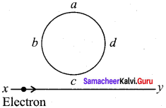
(а) The current will reverse its direction as the electron goes past the coil
(b) No current will be induced Electron
(c) abcd
(d) adcb
Answer:
(a) The current will reverse its direction as the electron goes past the coil
12th Physics Lesson 4 Book Back Answers Question 2.
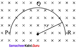
A thin semi-circular conducting ring (PQR) of radius r is falling with its plane vertical in a horizontal magnetic field B, as shown in the figure. The potential difference developed across the ring when its speed v, is- (NEET 2014)
(a) Zero
(b) \(\frac {{ Bvπr }^{2}}{ 2 }\)
(c) πrBv and R is at higher potential
(d) 2rBv and R is at higher potential
Answer:
(d) 2rBv and R is at higher potential
Samacheerkalvi.Guru 12th Physics Question 3.
The flux linked with a coil at any instant t is given by ΦB = 10t2 – 50t + 250. The induced emf at t = 3s is-
(a) -190 V
(b) -10 V
(c) 10 V
(d) 190 V
Answer:
(b) -10 V
Samacheer Kalvi 12th Physics Solutions Question 4.
When the current changes from +2A to -2A in 0.05 s, an emf of 8 V is induced in a coil. The co-efficient of self-induction of the coil is-
(a) 0.2 H
(b) 0.4 H
(c) 0.8 H
(d) 0.1 H
Answer:
(d) 0.1 H
Samacheer Kalvi 12th Physics Solution Book Question 5.
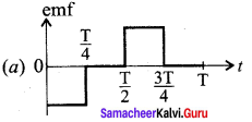
The current i flowing in a coil varies with time as shown in the figure. The variation of induced emf with time would be- (NEET-2011)
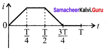
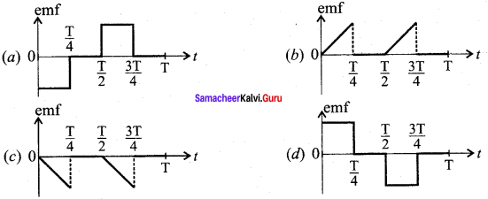
Answer:
Tn 12th Physics Solution Question 6.
A circular coil with a cross-sectional area of 4 cm2 has 10 turns. It is placed at the centre of a long solenoid that has 15 turns/cm and a cross-sectional area of 10 cm2. The axis of the coil coincides with the axis of the solenoid. What is their mutual inductance?
(a) 7.54 μH
(b) 8.54 μH
(c) 9.54 μH
(d) 10.54 μH
Answer:
(a) 7.54 μH
Samacheer Kalvi Guru 12th Physics Question 7.
In a transformer, the number of turns in the primary and the secondary are 410 and 1230, respectively. If the current in primary is 6A, then that in the secondary coil is-
(a) 2 A
(b) 18 A
(c) 12 A
(d) 1 A
Answer:
(a) 2 A
Physics Class 12 Chapter 4 Notes Question 8.
A step-down transformer reduces the supply voltage from 220 V to 11 V and increase the current from 6 A to 100 A. Then its efficiency is-
(a) 1.2
(b) 0.83
(c) 0.12
(d) 0.9
Answer:
(b) 0.83
Alternating Current Class 12 Notes Pdf Download Question 9.
In an electrical circuit, R, L, C and AC voltage source are all connected in series. When L is removed from the circuit, the phase difference between the voltage and current in the circuit is \(\frac { 1 }{ 2 }\). Instead, if C is removed from the circuit, the phase difference is again \(\frac { π }{ 3 }\). The power factor of the circuit is- (NEET 2012)
(a) \(\frac { 1 }{ 2 }\)
(b) \(\frac { 1 }{ √ 2 }\)
(c) 1
(d) \(\frac { √ 3 }{ 2 }\)
Answer:
(c) 1
Physics Solution Class 12 Samacheer Kalvi Question 10.
In a series RL circuit, the resistance and inductive reactance are the same. Then the phase difference between the voltage and current in the circuit is-
(a) \(\frac { π }{ 4 }\)
(b) \(\frac { π }{ 2 }\)
(c) \(\frac { π }{ 6 }\)
(d) zero
Answer:
(a) \(\frac { π }{ 4 }\)
Samacheer 12th Physics Solutions Question 11.
In a series resonant RLC circuit, the voltage across 100 Ω resistor is 40 V. The resonant frequency co is 250 rad/s. If the value of C is 4 μF, then the voltage across L is-
(a) 600 V
(b) 4000 V
(c) 400 V
(d) 1 V
Answer:
(c) 400 V
Question 12.
An inductor 20 mH, a capacitor 50 μF and a resistor 40 Ω are connected in series across a source of emf v = 10 sin 340 t. The power loss in AC circuit is-
(a) 0.76 W
(b) 0.89 W
(c) 0.46 W
(d) 0.67 W
Answer:
(c) 0.46 W
Questions 13.
The instantaneous values of alternating current and voltage in a circuit are i = \(\frac { 1 }{ √ 2 }\) = sin(100πt) A and v = \(\frac { 1 }{ √ 2 }\) sin \(\left(100 \pi t+\frac{\pi}{3}\right)\) V. The average power in watts consumed in the circuit is-
(IIT Main 2012)
(a) \(\frac { 1 }{ 4 }\)
(b) \(\frac { √3 }{ 4 }\)
(c) \(\frac { 1 }{ 2 }\)
(d) \(\frac { 1 }{ 8 }\)
Answer:
(d) \(\frac { 1 }{ 8 }\)
Question 14.
In an oscillating LC circuit, the maximum charge on the capacitor is Q. The charge on the capacitor when the energy is stored equally between the electric and magnetic fields is-
(a) \(\frac { Q }{ 2 }\)
(b) \(\frac { Q }{ √3 }\)
(c) \(\frac { Q }{ √2 }\)
(d) \(\frac { Q }{ 2 }\)
Answer:
(c) \(\frac { Q }{ √2 }\)
Question 15.
\(\frac { 20 }{{ π }^{2}}\) H inductor is connected to a capacitor of capacitance C. The value of C in order to impart maximum power at 50 Hz is-
(a) 50 μF
(b) 0.5 μF
(c) 500 μF
(d) 5 μF
Answer:
(d) 5 μF
Samacheer Kalvi 12th Physics Electromagnetic Induction and Alternating Current Short Answer Questions
Question 1.
What is meant by electromagnetic induction?
Answer:
Whenever the magnetic flux linked with a closed coil changes, an emf (electromotive force) is induced and hence an electric current flows in the circuit.
Question 2.
State Faraday’s laws of electromagnetic induction.
Answer:
First law:
Whenever magnetic flux linked with a closed circuit changes, an emf is induced in the circuit.
Second law:
The magnitude of induced emf in a closed circuit is equal to the time rate of change of magnetic flux linked with the circuit.
Question 3.
State Lenz’s law.
Answer:
State Lenz’s law:
Lenz’s law states that the direction of the induced current is such that it always opposes the cause responsible for its production.
Question 4.
State Fleming’s right hand rule.
Answer:
The thumb, index finger and middle finger of right hand are stretched out in mutually perpendicular directions. If the index finger points the direction of the magnetic field and the Electromagnetic Induction and Alternating Current thumb indicates the direction of motion of the conductor, then the middle finger will indicate the direction of the induced current.
Question 5.
How is Eddy current produced? How do they flow in a conductor?
Answer:
Even for a conductor in the form of a sheet or plate, an emf is induced when magnetic flux linked with it changes. But the difference is that there is no definite loop or path for induced current to flow away. As a result, the induced currents flow in concentric circular paths. As these electric currents resemble eddies of water, these are known as Eddy currents. They are also called Foucault currents.
Question 6.
Mention the ways of producing induced emf.
Answer:
Induced emf can be produced by changing magnetic flux in any of the following ways:
- By changing the magnetic field B
- By changing the area A of the coil and
- By changing the relative orientation 0 of the coil with magnetic field
Question 7.
What for an inductor is used? Give some examples.
Answer:
Inductor is a device used to store energy in a magnetic field when an electric current flows through it. The typical examples are coils, solenoids and toroids.
Question 8.
What do you mean by self-induction?
Answer:
If the magnetic flux is changed by changing the current, an emf is induced in that same coil. This phenomenon is known as self-induction.
Question 9.
What is meant by mutual induction?
Answer:
When an electric current passing through a coil changes with time, an emf is induced in the neighbouring coil. This phenomenon is known as mutual induction.
Question 10.
Give the principle of AC generator.
Answer:
Alternators work on the principle of electromagnetic induction. The relative motion between a conductor and a magnetic field changes the magnetic flux linked with the conductor which in turn, induces an emf. The magnitude of the induced emf is given by Faraday’s law of electromagnetic induction and its direction by Fleming’s right hand rule.
Question 11.
List out the advantages of stationary armature-rotating field system of AC generator.
Answer:
- The current is drawn directly from fixed terminals on the stator without the use of brush contacts.
- The insulation of stationary armature winding is easier.
- The number of sliding contacts (slip rings) is reduced. Moreover, the sliding contacts are used for low-voltage DC Source.
- Armature windings can be constructed more rigidly to prevent deformation due to any mechanical stress.
Question 12.
What are step-up and step-down transformers?
Answer:
If the transformer converts an alternating current with low voltage into an alternating current with high voltage, it is called step-up transformer. On the contrary, if the transformer converts alternating current with high voltage into an alternating current with low voltage, then it is called step-down transformer.
Question 13.
Define average value of an alternating current.
Answer:
The average value of alternating current is defined as the average of all values of current over a positive half-cycle or negative half-cycle.
Question 14.
How will you define RMS value of an alternating current?
Answer:
RMS value of alternating current is defined as that value of the steady current which when flowing through a given circuit for a given time produces the same amount of heat as produced by the alternating current when flowing through the same circuit for the same time.
Question 15.
What are phasors?
Answer:
A sinusoidal alternating voltage (or current) can be represented by a vector which rotates about the origin in anti-clockwise direction at a constant angular velocity ω. Such a rotating vector is called a phasor.
Question 16.
Define electric resonance.
Answer:
When the frequency of the applied alternating source is equal to the natural frequency of the RLC circuit, the current in the circuit reaches its maximum value. Then the circuit is said to be in electrical resonance.
Question 17.
What do you mean by resonant frequency?
Answer:
When the frequency of the applied alternating source (ωr) is equal to the natural frequency \(\left[\frac{1}{\sqrt{L C}}\right]\) of the RLC circuit, the current in the circuit reaches its maximum value. Then the circuit is said to be in electrical resonance. The frequency at which resonance takes place is called resonant frequency. Resonant angular frequency, ωr = \(\frac { 1 }{ \sqrt { LC } } \)
Question 18.
How will you define Q-factor?
Answer:
It is defined as the ratio of voltage across L or C to the applied voltage.
![]()
Question 19.
What is meant by wattles current?
Answer:
The component of current (IRMS sin φ), which has a phase angle of \(\frac { π }{ 2 }\) with the voltage is called reactive component. The power consumed is zero. So that it is also known as ‘Wattless’ current.
Question 20.
Give any one definition of power factor.
Answer:
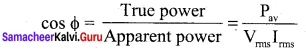
The power factor is defined as the ratio of true power to the apparent power of an a.c. circuit. It is equal to the cosine of the phase angle between current and voltage in the a.c. circuit.
Question 21.
What are LC oscillations?
Answer:
Whenever energy is given to a LC circuit, the electrical oscillations of definite frequency are generated. These oscillations are called LC oscillations. During LC oscillations, the total energy remains constant. It means that LC oscillations take place in accordance with the law of conservation of energy.
Samacheer Kalvi 12th Physics Electromagnetic Induction and Alternating Current Long Answer Questions
Question 1.
Establish the fact that the relative motion between the coil and the magnet induces an emf in the coil of a closed circuit.
Answer:
Whenever the magnetic flux linked with a closed coil changes, an emf (electromotive force) is induced and hence an electric current flows in the circuit.
The relative motion between the coil and the magnet induces:
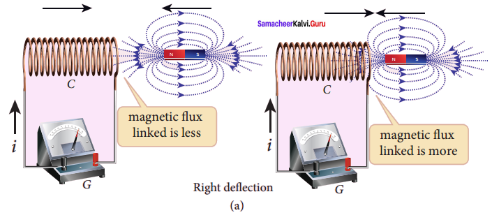
In the first experiment, when a bar magnet is placed close to a coil, some of the magnetic field lines of the bar magnet pass through the coil i.e., the magnetic flux is linked with the coil. When the bar magnet and the coil approach each other, the magnetic flux linked with the coil increases. So this increase in magnetic flux induces an emf and hence a transient electric current flows in the circuit in one direction (Figure(a)).
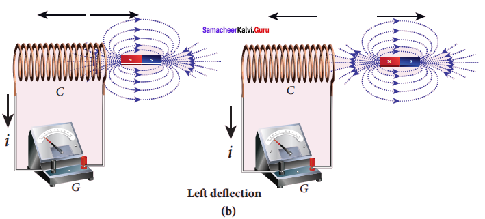
At the same time, when they recede away from one another, the magnetic flux linked with the coil decreases. The decrease in magnetic flux again induces an emf in opposite direction and hence an electric current flows in opposite direction (Figure (b)). So there is deflection in the galvanometer when there is a relative motion between the coil and the magnet.
In the second experiment, when the primary coil P carries an electric current, a magnetic field is established around it. The magnetic lines of this field pass through itself and the neighbouring secondary coil S.
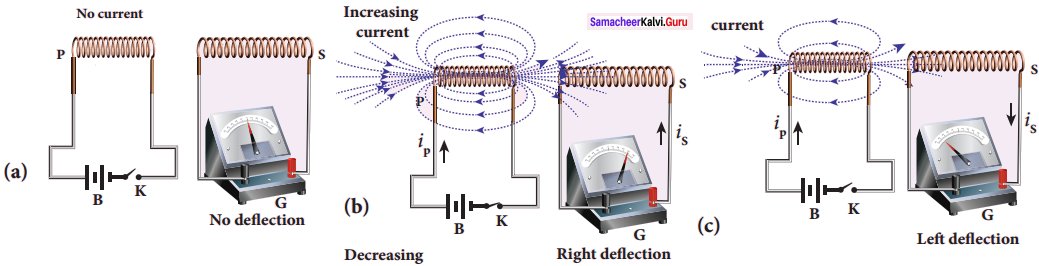
When the primary circuit is open, no electric current flows in it and hence the magnetic flux linked with the secondary coil is zero (Figure(a)).
However, when the primary circuit is closed, the increasing current builds up a magnetic field around the primary coil. Therefore, the magnetic flux linked with the secondary coil increases. This increasing flux linked induces a transient electric current in the secondary coil (Figure(b)).
When the electric current in the primary coil reaches a steady value, the magnetic flux linked with the secondary coil does not change and the electric current in the secondary coil will disappear. Similarly, when the primary circuit is broken, the decreasing primary current induces an electric current in the secondary coil, but in the opposite direction (Figure (c)). So there is deflection in the galvanometer whenever there is a change in the primary current
Question 2.
Give an illustration of determining direction of induced current by using Lenz’s law.
Answer:
Illustration 1:
Consider a uniform magnetic field, with its field lines perpendicular to the plane of the paper and pointing inwards. These field lines are represented by crosses (x) as shown in figure (a). A rectangular metallic frame ABCD is placed in this magnetic field, with its plane perpendicular to the field. The arm AB is movable so that it can slide towards right or left.
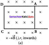
If the arm AB slides to our right side, the number of field lines (magnetic flux) passing through the frame ABCD increases and a current is induced. As suggested by Lenz’s law, the induced current opposes this flux increase and it tries to reduce it by producing another magnetic field pointing outwards i.e., opposite to the existing magnetic field.
The magnetic lines of this induced field are represented by circles in the figure (b). From the direction of the magnetic field thus produced, the direction of the induced current is found to be anti-clockwise by using right-hand thumb rule.
The leftward motion of arm AB decreases magnetic flux. The induced current, this time, produces a magnetic field in the inward direction i.e., in the direction of the existing magnetic field (figure (c)). Therefore, the flux decrease is opposed by the flow of induced current. From this, it is found that induced current flows in clockwise direction.
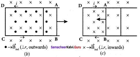
Illustration 2:
Let us move a bar magnet towards the solenoid, with its north pole pointing the solenoid as shown in figure (b). This motion increases the magnetic flux of the coil which in turn, induces an electric current. Due to the flow of induced current, the coil becomes a magnetic dipole whose two magnetic poles are on either end of the coil.
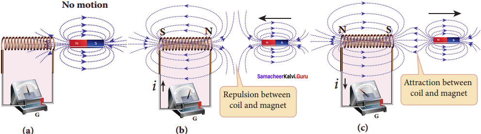
In this case, the cause producing the induced current is the movement of the magnet. According to Lenz’s law, the induced current should flow in such a way that it opposes the movement of the north pole towards coil. It is possible if the end nearer to the magnet becomes north pole (figure (b)).
Then it repels the north pole of the bar magnet and opposes the movement of the magnet. Once pole ends are known, the direction of the induced current could be found by using right hand thumb rule. When the bar magnet is withdrawn, the nearer end becomes south pole which attracts north pole of the bar magnet, opposing the receding motion of the magnet (figure (c)). Thus the direction of the induced current can be found from Lenz’s law.
Question 3.
Show that Lenz’s law is in accordance with the law of conservation of energy.
Answer:
Conservation of energy:
The truth of Lenz’s law can be established on the basis of the law of conservation of energy. According to Lenz’s law, when a magnet is moved either towards or away from a coil, the induced current produced opposes its motion. As a result, there will always be a resisting force on the moving magnet.
Work has to be done by some external agency to move the magnet against this resisting force. Here the mechanical energy of the moving magnet is converted into the electrical energy which in turn, gets converted into Joule heat in the coil i.e., energy is converted from one form to another.
Question 4.
Obtain an expression for motional emf from Lorentz force.
Answer:
Motional emf from Lorentz force:
Consider a straight conducting rod AB of length l in a uniform magnetic field \(\vec { B } \) which is directed perpendicularly into the plane of the paper. The length of the rod is normal to the magnetic field. Let the rod move with a constant velocity \(\vec { v } \) towards right side.
When the rod moves, the free electrons present in it also move with same velocity \(\vec { v } \) in \(\vec { B } \). As a result, the Lorentz force acts on free electrons in the direction from B to A and is given by the relation
\(\vec { F } \)B = -e(\(\vec { v } \) x \(\vec { B } \) ) ……. (1)
The action of this Lorentz force is to accumulate the free electrons at the end A. This accumulation of free electrons produces a potential difference across the rod which in turn establishes an electric field E directed along BA. Due to the electric field E, the coulomb force starts acting on the free electrons along AB and is given by
\(\vec { F } \)E = -e\(\vec { E } \) ……. (2)
The magnitude of the electric field \(\vec { E } \) keeps on increasing as long as accumulation of electrons at the end A continues. The force \(\vec { F } \)E also increases until equilibrium is reached. At equilibrium, the magnetic Lorentz force \(\vec { F } \)B and the coulomb force \(\vec { F } \)E balance each other and no further accumulation of free electrons at the end A takes place, i.e.,
\(\left| \vec { { F }_{ B } } \right| \) = \(\left| \vec { { F }_{ E } } \right| \)
![]()
vB sin 90° = E
vB = E ……. (3)
The potential difference between two ends of the rod is
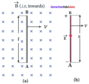
Figure: Motional emf from Lorentz force
V = El
V = vBl
Thus the Lorentz force on the free electrons is responsible to maintain this . potential difference and hence produces an emf
ε = Blv ….. (4)
As this emf is produced due to the movement of the rod, it is often called as motional emf.
Question 5.
Using Faraday’s law of electromagnetic induction, derive an equation for motional emf.
Answer:
Motional emf from Faraday’s law:
Let us consider a rectangular conducting loop of width l in a uniform magnetic field \(\vec { B } \) which is perpendicular to the plane of the loop and is directed inwards. A part of the loop is in the magnetic field while the remaining part is outside the field.
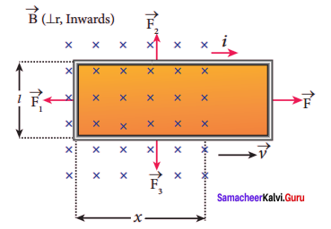
Figure: Motional emf from Faraday’s law
When the loop is pulled with a constant velocity \(\vec { v } \) to the right, the area of the portion of the loop within the magnetic field will decrease. Thus, the flux linked with the loop will also decrease. According to Faraday’s law, an electric current is induced in the loop which flow’s in a direction so as to oppose the pull of the loop.
Let x be the length of the loop which is still within the magnetic field, then its area is lx. The magnetic flux linked with the loop is
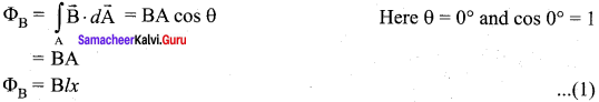
As this magnetic flux decreases due to the movement of the loop, the magnitude of the induced emf is given by
ε = \(\frac {{ dΦ }_{B}}{ dt }\) = \(\frac { d }{ dt }\) (Blx)
Here, both B and l are constants. Therefore,
ε = Bl \(\frac { dx}{ dl }\) = Blv …… (2)
where v = \(\frac { dx}{ dt }\) is the velocity of the loop. This emf is known as motional emf since it is produced due to the movement of the loop in the magnetic field.
Question 6.
Give the uses of Foucault current.
Answer:
Though the production of eddy current is undesirable in some cases, it is useful in some other cases. A few of them are
- Induction stove
- Eddy current brake
- Eddy current testing
- Electromagnetic damping
1. Induction stove:
Induction stove is used to cook the food quickly and safely with less energy consumption. Below the cooking zone, there is a tightly wound coil of insulated wire. The cooking pan made of suitable material, is placed over the cooking zone.
When the stove is switched on, an alternating current flowing in the coil produces high frequency alternating magnetic field which induces very strong eddy currents in the cooking pan. The eddy currents in the pan produce so much of heat due to Joule heating which is used to cook the food.
2. Eddy current brake:
This eddy current braking system is generally used in high speed trains and roller coasters. Strong electromagnets are fixed just above the rails. To stop the train, electromagnets are switched on. The magnetic field of these magnets induces eddy currents in the rails which oppose or resist the movement of the train. This is Eddy current linear brake.
In some cases, the circular disc, connected to the wheel of the train through a common shaft, is made to rotate in between the poles of an electromagnet. When there is a relative motion between the disc and the magnet, eddy currents are induced in the disc which stop the train. This is Eddy current circular brake.
3. Eddy current testing:
It is one of the simple non-destructive testing methods to find defects like surface cracks and air bubbles present in a specimen. A coil of insulated wire is given an alternating electric current so that it produces an alternating magnetic field.
When this coil is brought near the test surface, eddy current is induced in the test surface. The presence of defects causes the change in phase and amplitude of the eddy current that can be detected by some other means. In this way, the defects present in the specimen are identified.
4. Electro magnetic damping:
The armature of the galvanometer coil is wound on a soft iron cylinder. Once the armature is deflected, the relative motion between the soft iron cylinder and the radial magnetic field induces eddy current in the cylinder. The damping force due to the flow of eddy current brings the armature to rest immediately and then galvanometer shows a steady deflection. This is called electromagnetic damping.
Question 7.
Define self-inductance of a coil interns of (i) magnetic flux and (ii) induced emf.
Answer:
Self-inductance or simply inductance of a coil is defined as the flux linkage of the coil when 1A current flows through it.
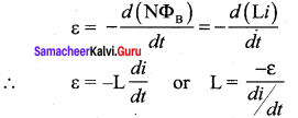
When the current i changes with time, an emf is induced in it. From Faraday’s law of electromagnetic induction, this self-induced emf is given by
ε = –\(\frac{d\left(\mathrm{N} \Phi_{\mathrm{B}}\right)}{d t}\) = –\(\frac { d(Li)}{ dt }\)
∴ ε = -L\(\frac { di}{ dt }\) or L = \(\frac { -ε}{ di/dt }\)
The negative sign in the above equation means that the self-induced emf always opposes the change in current with respect to time. If \(\frac { di}{ dt }\) = 1 As-1, then L= -ε. Inductance of a coil is also defined as the opposing emf induced in the coil when the rate of change of current through the coil is 1 A s-1.
Question 8.
How will you define the unit of inductance?
Answer:
Unit of inductance: Inductance is a scalar and its unit is Wb A-1 or V s A-1. It is also measured in henry (H).
1 H = 1 Wb A-1 = 1 V s A-1
The dimensional formula of inductance is M L2 T-2A-2.
If i = 1 A and NΦB = 1 Wb turns, then L = 1 H.
Therefore, the inductance of the coil is said to be one henry if a current of 1 A produces unit flux linkage in the coil.
If \(\frac { di}{ dt }\) = 1 As-1 and ε = -1 V, then L = 1 H.
Therefore, the inductance of the coil is one henry if a current changing at the rate of 1 A s-1 induces an opposing emf of 1 V in it.
Question 9.
What do you understand by self-inductance of a coil? Give its physical significance.
Answer:
Self-inductance or simply inductance of a coil is defined as the flux linkage of the coil when 1A current flows through it.
When the current i changes with time, an emf is induced in it. From Faraday’s law of electromagnetic induction, this self-induced emf is given by
Physical significance of inductance:
When a circuit is switched on, the increasing current induces an emf which opposes the growth of current in a circuit. Likewise, when circuit is broken, the decreasing current induces an emf in the reverse direction. This emf now opposes the decay of current.
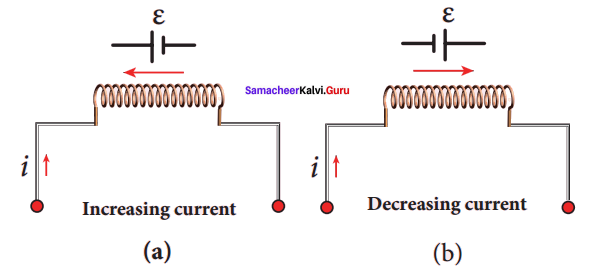
Figure: Induced emf ε opposes the changing current i
Thus, inductance of the coil opposes any change in current and tries to maintain the original state.
Question 10.
Assuming that the length of the solenoid is large when compared to its diameter, find the equation for its inductance.
Answer:
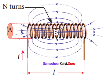
Self-inductance of a long solenoid:
Consider a long solenoid of length l and cross-sectional area A. Let n be the number of turns per unit length (or turn density) of the solenoid. When an electric current i is passed through the solenoid, a magnetic field is produced by it which is almost uniform and is directed along the axis of the solenoid. The magnetic field at any point inside the solenoid is given by
B = μ0ni
As this magnetic field passes through the solenoid, the windings of the solenoid are linked by the field lines. The magnetic flux passing through each turn is
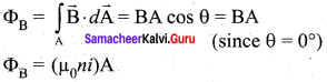
The total magnetic flux linked or flux linkage of the solenoid with N turns (the total number of turns N is given by N = nl) is
NΦB = n (nl) (μ0ni)A
NΦB = (μ0n2Al)i ….. (1)
From the self induction
NΦB = LI ….. (2)
Comparing equations (1) and (2), we have L = μ0n2Al
From the above equation, it is clear that inductance depends on the geometry of the solenoid (turn density n, cross-sectional area A, length l) and the medium present inside the solenoid. If the solenoid is filled with a dielectric medium of relative permeability μr, then
L = μ0
L = μn0μrn2Al
Question 11.
An inductor of inductance L carries an electric current i. How much energy is stored while establishing the current in it?
Answer:
Energy stored in an inductor:
Whenever a current is established in the circuit, the inductance opposes the growth of the current. In order to establish a current in the circuit, work is done against this opposition by some external agency. This work done is stored as magnetic potential energy.
Let us assume that electrical resistance of the inductor is negligible and inductor effect alone is considered. The induced emf e at any instant t is
ε = -L\(\frac { di}{ dt }\) …… (1)
Let dW be work done in moving a charge dq in a time dt against the opposition, then
dW = -εdq = -εidi = εidi [∵dq = idt]
Substituting for s value from equation (1)
= – \(\left(-\mathrm{L} \frac{d i}{d t}\right)\) idt
dW = Lid …… (2)
Total work done in establishing the current i is
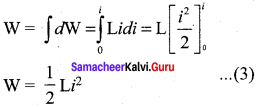
This work done is stored as magnetic potential energy.
UB = \(\frac { 1 }{ 2 }\) Li2 …….. (4)
Question 12.
Show that the mutual inductance between a pair of coils is same (M12 = M21).
Answer:
Mutual induction:
When an electric current passing through a coil changes with time, an emf is induced in the neighbouring coil. This phenomenon is known as mutual induction and the emf is called mutually induced emf.
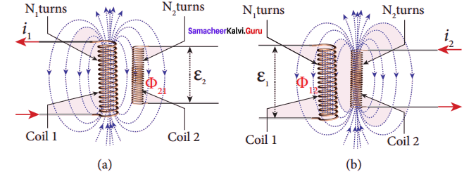
Consider two coils which are placed close to each other. If an electric current i1 is sent through coil 1, the magnetic field produced by it is also linked with coil 2. Let Φ21 be the magnetic flux linked with each turn of the coil 2 of N2 turns due to coil 1, then the total flux linked with coil 2 (N2Φ21) is proportional to the current i1 in the coil 1.
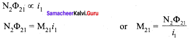
The constant of proportionality M21 is the mutual inductance of the coil 2 with respect to coil 1. It is also called as coefficient of mutual induction. If i1 = 1A, then M21 = N2Φ21.
Therefore, the mutual inductance M21 is defined as the flux linkage of the coil 2 when 1A current flows through coil 1. When the current changes with time, an emf ε2 is induced in coil 2. From Faraday’s law of electromagnetic induction, this mutually induced emf ε2 is given by
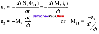
The negative sign in the above equation shows that the mutually induced emf always opposes the change in current i, with respect to time. If \(\frac { di }{ dt }\) = 1 As-1, then M21 = -ε2. Mutual inductance M21, is also defined as the opposing emf induced in the coil 2 when the rate of change of current through the coil 1 is 1 As-1. Similarly, if an electric current i2 through coil 2 changes with time, then emf ε1 is induced in coil 1. Therefore,
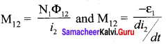
where M12 is the mutual inductance of the coil 1 with respect to coil 2. It can be shown that for a given pair of coils, the mutual inductance is same, i.e., M21 = M12 = M.
In general, the mutual induction between two coils depends on size, shape, the number of turns of the coils, their relative orientation and permeability of the medium.
Question 13.
How will you induce an emf by changing the area enclosed by the coil?
Answer:
Induction of emf by changing the area of the coil:
Consider a conducting rod of length 1 moving with a velocity v towards left on a rectangular metallic framework. The whole arrangement is placed in a uniform magnetic field \(\vec { B } \) whose magnetic lines are perpendicularly directed into the plane of the paper. As the rod moves from AB to DC in a time dt, the area enclosed by the loop and hence the magnetic flux through the loop decreases.
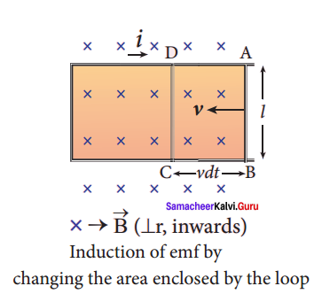
The change in magnetic flux in time dt is
dΦB = B x change in area
B x Area ABCD
= Blvdt since Area ABCD = l(vdt)
or \(\frac {{ dΦ }_{B}}{ dt }\) = Blv
As a result of change in flux, an emf is generated in the loop. The magnitude of the induced emf is
ε = \(\frac {{ dΦ }_{B}}{ dt }\) = Blv
This emf is called motional emf. The direction of induced current is found to be clockwise from Fleming’s right hand rule.
Question 14.
Show mathematically that the rotation of a coil in a magnetic field over one rotation induces an alternating emf of one cycle.
Answer:
Induction of emf by changing relative orientation of the coil with the magnetic field:
Consider a rectangular coil of N turns kept in a uniform magnetic field \(\vec { B } \) figure (a). The coil rotates in anti-clockwise direction with an angular velocity ω about an axis, perpendicular to the field. At time = 0, the plane of the coil is perpendicular to the field and the flux linked with the coil has its maximum value Φm = BA (where A is the area of the coil).
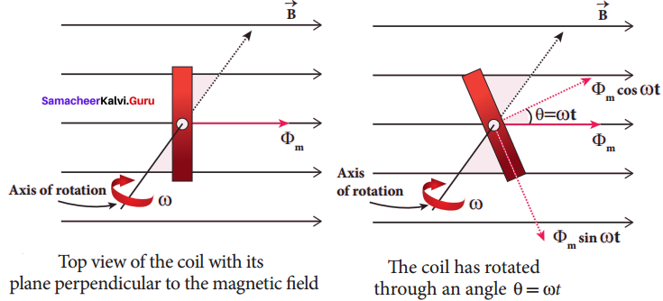
In a time t seconds, the coil is rotated through an angle θ (= ωt) in anti-clockwise direction. In this position, the flux linked is Φm cos ωt, a component of Φm normal to the plane of the coil (figure (b)). The component parallel to the plane (Φm sin ωt) has no role in electromagnetic induction. Therefore, the flux linkage at this deflected position is NΦB = NΦm cos ωt. According to Faraday’s law, the emf induced at that instant is
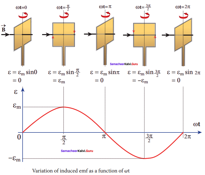
ε= \(\frac { d }{ dt }\) (NΦB ) = \(\frac { d }{ dt }\) (NΦm cos ωt)
= -NΦm (-sin ωt)ω = NΦm ω sin ωt
When the coil is rotated through 90° from initial position, sin ωt = 1, Then the maximum value of induced emf is
εm = NΦmω = NBAω since Φm = BA
Therefore, the value of induced emf at that instant is then given by
ε = εm sin ωt
It is seen that the induced emf varies as sine function of the time angle ωt. The graph between – induced emf and time angle for one rotation of coil will be a sine curve and the emf varying in this manner is called sinusoidal emf or alternating emf.
Question 15.
Elaborate the standard construction details of AC generator.
Answer:
Construction:
lternator consists of two major parts, namely stator and rotor. As their names suggest, stator is stationary while rotor rotates inside the stator. In any standard construction of commercial alternators, the armature winding is mounted on stator and the field magnet on rotor. The construction details of stator, rotor and various other components involved in them are given below.
(i) Stator:
The stationary part which has armature windings mounted in it is called stator. It has three components, namely stator frame, stator core and armature winding.
Stator frame:
This is the outer frame used for holding stator core and armature windings in proper position. Stator frame provides best ventilation with the help of holes provided in the frame itself.
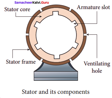
Stator core:
Stator core or armature core is made up of iron or steel alloy. It is a hollow cylinder and is laminated to minimize eddy current loss. The slots are cut on inner surface of the core to accommodate armature windings.
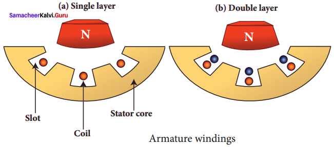
Armature winding:
Armature winding is the coil, wound on slots provided in the armature core. One or more than one coil may be employed, depending on the type of alternator. Two types of windings are commonly used. They are (i) single-layer winding and (ii) double-layer winding. In single-layer winding, a slot is occupied by a coil as a single layer. But in double-layer winding, the coils are split into two layers such as top and bottom layers.
(ii) Rotor:
Rotor contains magnetic field windings. The magnetic poles are magnetized by DC source. The ends of field windings are connected to a pair of slip rings, attached to a common shaft about which rotor rotates. Slip rings rotate along with rotor. To maintain connection between the DC source and field windings, two brushes are used which . continuously slide over the slip rings.
There are 2 types of rotors used in alternators:
- salient pole rotor
- cylindrical pole rotor.
1. Salient pole rotor:
The word salient means projecting. This rotor has a number of projecting poles having their bases riveted to the rotor. It is mainly used in low-speed alternators.
2. Cylindrical pole rotor:
This rotor consists of a smooth solid cylinder. The slots are cut on the outer surface of the cylinder along its length. It is suitable for very high speed alternators.
The frequency of alternating emf induced is directly proportional to the rotor speed. In order to maintain the frequency constant, the rotor must run at a constant speed. These are standard construction details of alternators.
Question 16.
Explain the working of a single-phase AC generator with necessary diagram.
Answer:
Single phase AC generator: In a single phase AC generator, the armature conductors are connected in series so as to form a single circuit which generates a single-phase alternating emf and hence it is called single-phase alternator.
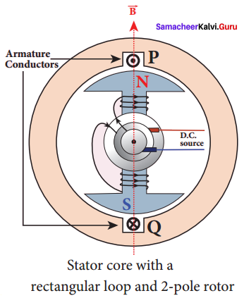
The simplified version of a AC generator is discussed here. Consider a stator core consisting of 2 slots in which 2 armature conductors PQ and RS are mounted to form single-turn rectangular loop PQRS. Rotor has 2 salient poles with field windings which can be magnetized by means of DC source.
Working:
The loop PQRS is stationary and is perpendicular to the plane of the paper. When field windings are excited, magnetic field is produced around it. The direction of magnetic field passing through the armature core. Let the field magnet be rotated in clockwise direction by the prime mover. The axis of rotation is perpendicular to the plane of the paper.
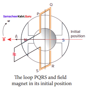
Assume that initial position of the field magnet is horizontal. At that instant, the direction of magnetic field is perpendicular to the plane of the loop PQRS. The induced emf is zero. This is represented by origin O in the graph between induced emf and time angle.
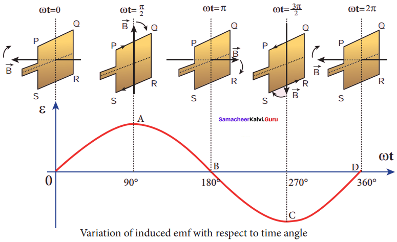
When field magnet rotates through 90°, magnetic field becomes parallel to PQRS. The induced cmfs across PQ and RS would become maximum. Since they are connected in series, emfs are added up and the direction of total induced emf is given by Fleming’s right hand rule. Care has to be taken while applying this rule; the thumb indicates the direction of the motion of the conductor with respect to field.
For clockwise rotating poles, the conductor appears to be rotating anti-clockwise. Hence, thumb should point to the left. The direction of the induced emf is at right angles to the plane of the paper. For PQ, it is downwards B and for RS upwards. Therefore, the current flows along PQRS. The point A in the graph represents this maximum emf.
For the rotation of 180° from the initial position, the field is again perpendicular to PQRS and the induced emf becomes zero. This is represented by point B. The field magnet becomes again parallel to PQRS for 270° rotation of field magnet. The induced emf is maximum but the direction is reversed. Thus the current flows along SRQP This is represented by point C.
On completion of 360°, the induced emf becomes zero and is represented by the point D. From the graph, it is clear that emf induced in PQRS is alternating in nature. Therefore, when field magnet completes one rotation, induced emf in PQRS finishes one cycle. For this construction, the frequency of the induced emf depends on the speed at which the field magnet rotates.
Question 17.
How are the three different emfs generated in a three-phase AC generator? Show the graphical representation of these three emfs.
Answer:
Three-phase AC generator:
Some AC generators may have more than one coil in the armature core and each coil produces an alternating emf. In these generators, more than one emf is produced. Thus they are called poly-phase generators. If there are two alternating emfs produced in a generator, it is called two-phase generator. In some AC generators, there are three separate coils, which would give three separate emfs. Hence they are called three-phase AC generators.
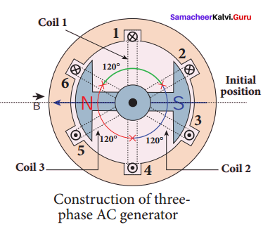
In the simplified construction of three-phase AC generator, the armature core has 6 slots, cut on its inner rim. Each slot is 60° away from one another. Six armature conductors are mounted in these slots. The conductors 1 and 4 are joined in series to form coil 1. The conductors 3 and 6 form coil 2 while the conductors 5 and 2 form coil 3. So, these coils are rectangular in shape and are 120° apart from one another.
The initial position of the field magnet is horizontal and field direction is perpendicular to the plane of the coil 1. As it is seen in single phase AC generator, when field magnet is rotated from that position in clockwise direction, alternating emf ε1 in coil 1 begins a cycle from origin O.
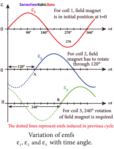
The corresponding cycle for alternating emf ε2 in coil 2 starts at point A after field magnet has rotated through 120°. Therefore, the phase difference between ε1 and ε2 is 120°. Similarly, emf ε3 in coil 3 would begin its cycle at point B after 240° rotation of field magnet from initial position. Thus these emfs produced in the three phase AC generator have 120° phase difference between one another.
Question 18.
Explain the construction and working of transformer.
Answer:
Construction and working of transformer:
Principle:
The principle of transformer is the mutual induction between two coils. That is, when an electric current passing through a coil changes with time, an emf is induced in the neighbouring coil.
Construction:
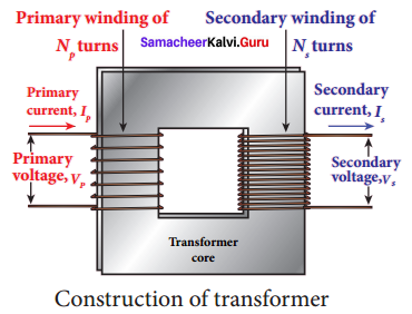
In the simple construction of transformers, there are two coils of high mutual inductance wound over the same transformer core. The core is generally laminated and is made up of a good magnetic material like silicon steel. Coils are electrically insulated but magnetically linked via transformer core.
The coil across which alternating voltage is applied is called primary coil P and the coil from which output power is drawn out is called secondary coil S. The assembled core and coils are kept in a container which is filled with suitable medium for better insulation and cooling purpose.
Working:
If the primary’ coil is connected to a source of alternating voltage, an alternating magnetic flux is set up in the laminated core. If there is no magnetic flux leakage, then whole of magnetic flux linked with primary coil is also linked with secondary coif This means that rate at which magnetic flux changes through each turn is same for both primary and secondary coils. As a result of flux change, emf is induced in both primary and secondary coils. The emf induced in the primary coil εp is almost equal and opposite to the applied voltage υp and is given by
υp = εp = -Np \(\frac {{ dΦ }_{B}}{ dt }\) …….. (1)
The frequency of alternating magnetic flux in the core is same as the frequency of the applied voltage. Therefore, induced emf in secondary will also have same frequency as that of applied voltage. The emf induced in the secondary coil eg is given by
εs = -Ns \(\frac {{ dΦ }_{B}}{ dt }\)
where Np and Ns are the number of turns in the primary and secondary coil, respectively. If the secondary circuit is open, then εs = υs where υs is the voltage across secondary coil.
υs εs = -Ns \(\frac {{ dΦ }_{B}}{ dt }\) ……… (2)
From equation (1) and (2),
\(\frac {{ υ }_{s}}{{ ε }{s}}\) = \(\frac {{ N }_{s}}{{ N }{p}}\) = K …….. (3)
This constant K is known as voltage transformation ratio. For an ideal transformer,
Input power υp ip = Output power υsis
where iυp and is are the currents in the primary and secondary coil respectively. Therefore,
\(\frac {{ υ }_{s}}{{ υ }{p}}\) = \(\frac {{ N }_{s}}{{ N }{p}}\) = \(\frac {{ i }_{p}}{{ i }{s}}\)
Equation (4) is written in terms of amplitude of corresponding quantities,
\(\frac {{ V }_{s}}{{ V }{p}}\) = \(\frac {{ N }_{s}}{{ N }{p}}\) = \(\frac {{ I }_{p}}{{ I }{s}}\) = K ……. (4)
(i) If Ns > Np ( or K > 1)
∴ Vs > Vp and Is < Ip.
This is sthe case of step-up transformer in which voltage is decreased and the corresponding current is decreased.
(ii) If Ns < Np (or K < 1)
∴ Vs < Vp and Is > Ip
This is step-down transformer where voltage is decreased and the current is increased.
Question 19.
Mention the various energy losses in a transformer.
Answer:
Energy losses in a transformer: Transformers do not have any moving parts so that its efficiency is much higher than that of rotating machines like generators and motors. But there are many factors which lead to energy loss in a transformer.
(i) Core loss or Iron loss:
This loss takes place in transformer core. Hysteresis loss and eddy current loss are known as core loss or Iron loss. When transformer core is magnetized and demagnetized repeatedly by the alternating voltage applied across primary coil, hysteresis takes place due to which some energy is lost in the form of heat.
Hysteresis loss is minimized by using steel of high silicon content in making transformer core. Alternating magnetic flux in the core induces eddy currents in it. Therefore there is energy loss due to the flow of eddy current, called eddy current loss which is minimized by using very thin laminations of transformer core.
(ii) Copper loss:
Transformer windings have electrical resistance. When an electric current flows through them, some amount of energy is dissipated due to Joule heating. This energy loss is called copper loss which is minimized by using wires of larger diameter.
(iii) Flux leakage:
Flux leakage happens when the magnetic lines of primary coil arc not completely linked with secondary coil. Energy loss due to this flux leakage is minimized by winding coils one over the other.
Question 20.
Give the advantage of AC in long distance power transmission with an example.
Answer:
Advantages of AC in long distance power transmission:
Electric power is produced in a t large scale at electric power stations with the help of AC generators. These power stations are classified based on the type of fuel used as thermal, hydro electric and nuclear power stations. Most of these stations are located at remote places.
Hence the electric power generated is transmitted over long distances through transmission lines to reach towns or cities where it is actually consumed. This process is called power transmission. But there is a difficulty during power transmission. A sizable fraction of electric power is lost due to Joule heating (i2R) in the transmission lines which are hundreds of kilometer long.
This power loss can be tackled either by reducing current i or by reducing resistance R of the transmission lines. The resistance R can be reduced with thick wires of copper or aluminium. But this increases the cost of production of transmission lines and other related expenses. So this way of reducing power loss is not economically viable.
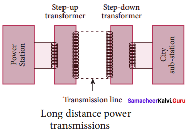
Since power produced is alternating in nature, there is a way out. The most important property of alternating voltage is that it can be stepped up and stepped down by using transformers could be exploited in reducing current and thereby reducing power losses to a greater extent.
At the transmitting point, the voltage is increased and the corresponding current is decreased by using step-up transformer. Then it is transmitted through transmission lines. This reduced current at high voltage reaches the destination without any appreciable loss.
At the receiving point, the voltage is decreased and the current is increased to appropriate values by using step-down transformer and then it is given to consumers. Thus power transmission is done efficiently and economically.
Illustration:
An electric power of 2 MW is transmitted to a place through transmission lines of total resistance, say R = 40 Ω, at two different voltages. One is lower voltage (10 kV) and the other is higher (100 kV). Let us now calculate and compare power losses in these two cases.
Case I:
P = 2 MW; R == 40 Ω; V = 10 kV Power,
Power, P = VI
∴ Current, I = \(\frac { P }{ V }\) = \(\frac {{ 2 × 10 }^{6}}{{ 10 × 10 }^{3}}\) 200 A
Power loss = Heat produced = I2R = (200)2 × 40 = 1.6 × 10⁶ W
% of power loss =\(\frac {{ 1.6 × 10 }^{6}}{{ 2 × 10 }^{6}}\) × 100% = 0.8 × 100% = 80%
Case II:
P = 2 MW; R == 40 Ω; V = 100 kV
∴ Current, I = \(\frac { P }{ V }\) = \(\frac {{ 2 × 10 }^{6}}{{ 100 × 10 }^{3}}\) 20 A
Power loss = Heat produced = I2R = (20)2 × 40 = 0.016 × 10⁶ W
% of power loss =\(\frac {{ 0.6 × 10 }^{6}}{{ 2 × 10 }^{6}}\) × 100% = 0.008 × 100% = 0.8%
Question 21.
Find out the phase relationship between voltage and current in a pure inductive circuit.
Answer:
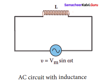
AC circuit containing only an inductor:
Consider a circuit containing a pure inductor of inductance L connected across an alternating voltage source. The alternating voltage is given by the equation.
υ = Vm sin ωt …(1)
The alternating current flowing through the inductor induces a self-induced emf or back emf in the circuit. The back emf is given by
Back emf, ε -L\(\frac { di }{ dt }\)
By applying Kirchoff’s loop rule to the purely inductive circuit, we get
υ + ε = 0
Vm sin ωt = L\(\frac { di }{ dt }\)
di = L\(\frac {{ V }_{m}}{ L }\) sin ωt dt
i = \(\frac {{ V }_{m}}{ L }\) \(\int { sin } \) ωt dt = \(\frac{{ V }_{m}}{ Lω }\) (-cos ωt) + constant
The integration constant in the above equation is independent of time. Since the voltage in the circuit has only time dependent part, we can set the time independent part in the current (integration constant) into zero.
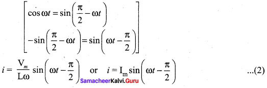
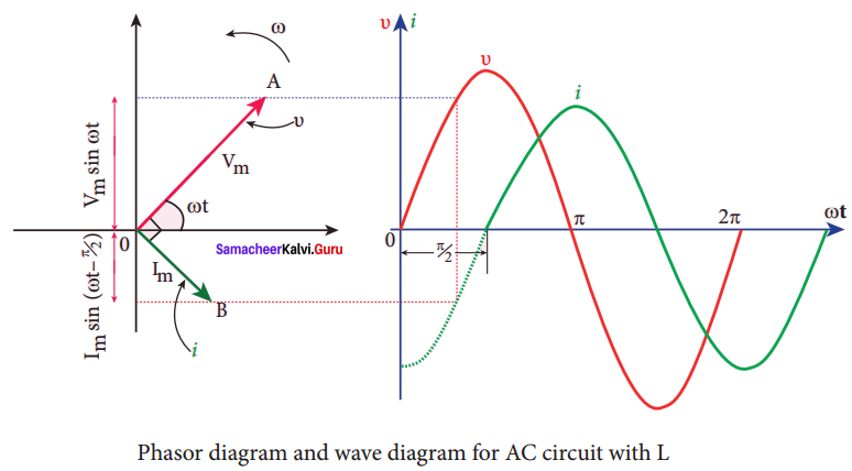
where \(\frac{{ V }_{m}}{ Lω }\) = Im, the peak value of the alternating current in the circuit. From equation (1) and (2), it is evident that current lags behind the applied voltage by \(\frac{π}{ 2 }\) in an inductive circuit.
This fact is depicted in the phasor diagram. In the wave diagram also, it is seen that current lags the voltage by 90°.
Inductive reactance XL:
The peak value of current Im is given by Im = \(\frac{{ V }_{m}}{ Lω }\) . Let us compare this equation with Im = \(\frac{{ V }_{m}}{ R }\) from resistive circuit. The equantity ωL Plays the same role as the resistance in resistive circuit. This is the resistance offered by the inductor, called inductive reactance (XL). It is measured in ohm.
XL = ωL
The inductive reactance (XL) varies directly as the frequency.
XL = 2πfL …….. (3)
where ƒ is the frequency of the alternating current. For a steady current, ƒ= 0. Therefore, XL = 0. Thus an ideal inductor offers no resistance to steady DC current.
Question 22.
Derive an expression for phase angle between the applied voltage and current in a series RLC circuit.
Answer:
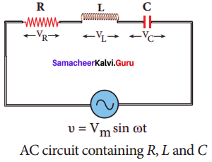
AC circuit containing a resistor, an inductor and a capacitor in series – Series RLC
circuit:
Consider a circuit containing a resistor of resistance R, a inductor of inductance L and a capacitor of capacitance C connected across an alternating voltage source. The applied alternating voltage is given by the equation.
υ = Vm sin ωt …… (1)
Let i be the resulting circuit current in the circuit at that instant. As a result, the voltage is developed across R, L and C.
We know that voltage across R (VR) is in phase with i, voltage across L (VL) leads i by π/2 and voltage across C (VC) lags i by π/2.
The phasor diagram is drawn with current as the reference phasor. The current is represented by the phasor
\(\vec { OI } \), VR by \(\vec { OA } \) ; VL by \(\vec { OB } \) and VC by \(\vec { OC } \).
The length of these phasors are
OI = Im, OA = ImR, OB = Im,XL; OC = ImXc
The circuit is cither effectively inductive or capacitive or resistive that depends on the value of V1 or Vc Let us assume that VL > VC. so that net voltage drop across L – C combination is VL < VC which is represented by a phasor \(\vec { AD } \).
By parallelogram law, the diagonal \(\vec { OE } \) gives the resultant voltage u of VR and (VL – VC ) and its length OE is equal to Vm. Therefore,
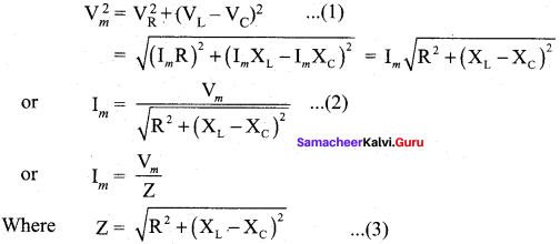
Z is called impedance of the circuit which refers to the effective opposition to the circuit current by the series RLC circuit. The voltage triangle and impedance triangle are given in the graphical figure.
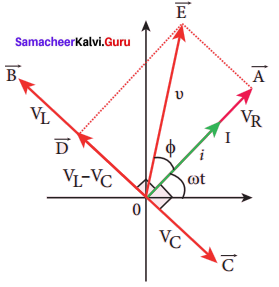
From phasor diagram, the phase angle between n and i is found out from the following relation
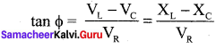
Special cases Figure: Phasor diagram for a series
(i) If XL > XC, (XL – XC) is positive and phase angle φ
is also positive. It means that the applied voltage leads the current by φ (or current lags behind voltage by φ). The circuit is inductive.
∴ υ = Vm sin ωt; i = Im sin(ωt + φ)
(ii) If XL < XC, (XL – XC) is negative and φ is also negative. Therefore current leads voltage by φ and the circuit is capacitive.
∴ υ = Vm sin ωt; i = Im sin(ωt + φ)
(iii) If XL = XC, φ is zero. Therefore current and voltage are in the same phase and the circuit is resistive.
∴ υ = Vm sin ωt; i = Im sin ωt
Question 23.
Define inductive and capacitive reactance. Give their units.
Answer:
Inductive reactance XL:
The peak value of current Im is given by Im = \(\frac{{ V }_{m}}{ Lω }\). Let us compare
this equation with Im \(\frac{{ V }_{m}}{ R }\) from resistive circuit. The quantity ωL plays the same role as the resistance R in resistive circuit. This is the resistance offered by the capacitor, called capacitive reactance (XL). It measured in ohm.
XL = ωL
Capacitive reactance XC:
The peak value of current I is given by Im = \(\frac{\mathrm{v}_{\mathrm{m}}}{1 / \mathrm{c} \omega}\). Let us compare this equation with Im = \(\frac{{ V }_{m}}{ R }\) from resistive circuit. The quantity \(\frac { 1 }{ ωC }\) plays the same role as the resistance R in resistive circuit. This is the resistance offered by the capacitor, called capacitive reactance (XC). It measured in ohm.
XC = \(\frac{ 1 }{ ωC }\).
Question 24.
Obtain an expression for average power of AC over a cycle. Discuss its special cases. Power of a circuit is defined as the rate of consumption of electric energy in that circuit.
Answer:
It is given by the product of the voltage and current. In an AC circuit, the voltage and current vary continuously with time. Let us first calculate the power at an instant and then it is averaged over a complete cycle.
The alternating voltage and alternating current in the series RLC circuit at an instant are given by
υ = Vm sin ωt and i = Im sin (ωt + 4>)
where φ is the phase angle between υ and i. The instantaneous power is then written as
P = υi = Vm Im sin ωt sin(ωt + φ)
= Vm Im sin ωt (sin ωt cos φ – cos ωt sin φ)
P = Vm Im (cos φ sin2 ωt – sin ωt cos ωt sin φ) …… (1)
Here the average of sin2 ωt over a cycle is \(\frac { 1 }{ 2 }\) and that of sin ωt cos ωt is zero. Substituting these values, we obtain average power over a cycle.
Pav = Vm Im cos φ x \(\frac { 1 }{ 2 }\) = \(\frac {{ V }_{m}}{ √2 }\) \(\frac {{ I }_{m}}{ √2 }\) cos φ
Pav = VRMS IRMS cos φ …… (2)
where VRMS IRMS is called apparent power and cos φ is power factor. The average power of an AC circuit is also known as the true power of the circuit.
Special Cases:
(i) For a purely resistive circuit, the phase angle between voltage and current is zero and cos
φ = 1.
∴ Pav = VRMS IRMS
(ii) For a purely inductive or capacitive circuit, the phase angle is ± \(\frac { π }{ 2 }\) and cos \(\left(\pm \frac{\pi}{2}\right)\) = 0
∴ Pav = 0
(iii) For series RLC circuit, the phase angle φ = tan-1 \(\left(\frac{\mathrm{x}_{\mathrm{L}}-\mathrm{x}_{\mathrm{c}}}{\mathrm{R}}\right)\)
∴ Pav = VRMS IRMS cos φ
(iv) For series RLC circuit at resonance, the phase angle is zero and cos φ = 1.
∴ Pav = VRMS IRMS
Question 25.
Show that the total energy is conserved during LC oscillations.
Answer:
Conservation of energy in LC oscillations: During LC oscillations in LC circuits, the energy of the system oscillates between the electric field of the capacitor and the magnetic field of the inductor. Although, these two forms of energy vary with time, the total energy remains constant. It means that LC oscillations take place in accordance with the law of conservation of energy.
Total energy,
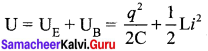
Let us consider 3 different stages of LC oscillations and calculate the total energy of the system.
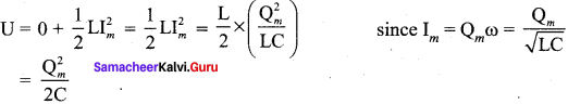
Case I:
When the charge in the capacitor, q = Qm and the current through the inductor, i = 0, the total energy is given by
![]()
The total energy is wholly electrical.
Case II:
When charge = 0; current = Im, the total energy is
The total energy is wholly electrical.
Case III:
When charge = q; current = i, the total energy is
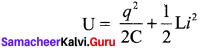
Since q = Qm cos ωt, i = \(\frac { bq }{ dt }\) = Qmω sin ωt. The negative sign in current indicates that the charge in the capacitor in the capacitor decreases with time.
From above three cases, it is clear that the total energy of the system remains constant.
Question 26.
Prove that energy is conserved during electromagnetic induction.
Answer:
The mechanical energy of the spring-mass system is given by
![]()
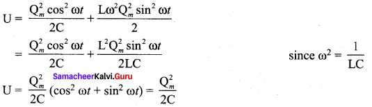
The energy E remains constant for varying values of x and v. Differentiating E with respect to time, we get
This is the differential equation of the oscillations of the spring-mass system. The general solution of equation (2) is of the form
x(t) = Xm cos (ωt + φ) …… (3)
where Xm is the maximum value of x(t), ω, the angular frequency and φ, the phase constant. Similarly, the electromagnetic energy of the LC system is given by
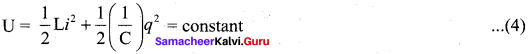
Differentiating U with respect to time, we get
Equation (2) and (5) are proved the energy of electromagnetic induction is conserved.
Question 27.
Compare the electromagnetic oscillations of LC circuit with the mechanical oscillations of block spring system to find the expression for angular frequency of LC oscillators mathematically.
Answer:
The mechanical energy of the spring-mass system is given by
![]()
The energy E remains constant for varying values of x and v. Differentiating E with respect to time, we get
This is the differential equation of the oscillations of the spring-mass system. The general solution of equation (2) is of the form
x(t) = Xm cos (ωt + φ) …… (3)
where Xm is the maximum value of x(t), ω, the angular frequency and φ, the phase constant. Similarly, the electromagnetic energy of the LC system is given by
Differentiating U with respect to time, we get
Equation (2) and (5) are proved the energy of electromagnetic induction is conserved.
q(t) = Qm cos (ωt + φ) …… (6)
where Qm is the maximum value of q(t), ω, the angular frequency and φ, the phase constant.
Current in the LC circuit:
The current flowing in the LC circuit is obtained by differentiating q(t) with respect to time.
i(t) = \(\frac { dq }{ dt }\) = \(\frac { d }{ dt }\) [Qm cos (ωt + φ)] = Qm ω sin (ωt + φ) since Im = Qmω
(or)
i(t) -Im sin (ωt + φ) ……. (7)
The equation (7) clearly shows that current varies as a function of time t. In fact, it is a sinusoidally varying alternating current with angular frequency ω.
Angular frequency of LC oscillations:
By differentiating equation (6) twice, we get
\(\frac { { d }^{ 2 }q }{ dt } \) = -Qmω2 cos (ωt + φ) …….. (8)
Substituting equations (6) and (8) in equation (5),
we obtain L[-Qmω2 cos (ωt + φ)] + \(\frac { 1 }{ C }\) Qm cos (ωt + φ) = 0
Rearranging the terms, the angular frequency of LC oscillations is given by
ω = \(\frac { 1 }{ \sqrt { LC } } \) …… (9)
This equation is the same as that obtained from qualitative analogy.
Samacheer Kalvi 12th Physics Electromagnetic Induction and Alternating Current Numerical Problems
Question 1.
A square coil of side 30 cm with 500 turns is kept in a uniform magnetic field of 0.4 T. The plane of the coil is inclined at an angle of 30° to the field. Calculate the magnetic flux through the coil.
Solution:
Square coil of side (a) = 30 cm = 30 × 10-2m
Area of square coil (A) = a2 = (30 × 10-2)2 = 9 × 10⁻² m2
Number of turns (N) = 500
Magnetic field (B) = 0.4 T
Angular between the field and coil (θ) = 90 – 30 = 60°
Magnetic flux (Φ) = NBA cos 0 = 500 × 0.4 × 9 × 10-2 × cos 60° = 18 × \(\frac { 1 }{ 2 }\)
Φ = 9 W b
Question 2.
A straight metal wire crosses a magnetic field of flux 4 mWb in a time 0.4 s. Find the magnitude of the emf induced in the wire.
Solution:
Magnetic flux (Φ) = 4 m Wb = 4 × 10⁻³ Wb
time (t) = 0.4 s
The magnitude of induced emf (e) = \(\frac { dΦ }{ dt }\) = \(\frac {{ 4 × 10 }^{-3}}{ 0.4 }\) 10-2
e = 10 mV
Question 3.
The magnetic flux passing through a coil perpendicular to its plane is a function of time and is given by OB = (2t3 + 4t2 + 8t + 8) Wb. If the resistance of the coil is 5 Ω, determine the induced current through the coil at a time t = 3 second.
Solution:
Magnetic flux (ΦB) = (2t3 + 8t2 + 8t + 8)Wb
Resistance of the coil (R) = 5 Ω
time (t) = 3 second
Induced current through the coil, I = \(\frac { e }{ R }\)
Induced emf, e = \(\frac {{ dΦ }_{B}}{ dt }\) = \(\frac { d }{ dt }\) ((2t3 + 4t2 + 8t + 8) = 6t2 + 8t + 8
Here time (t) = 3 second
e = 6(3)2 + 8 × 3 + 8 = 54 + 24 + 8 = 86 V
∴ Induced current through the coil, I = \(\frac { e }{ R }\) = \(\frac { 86 }{ 5 }\) = 17.2 A
Question 4.
A closely wound coil of radius 0.02 m is placed perpendicular to the magnetic field. When the magnetic field is changed from 8000 T to 2000 T in 6 s, an emf of 44 V is induced. Calculate the number of turns in the coil.
Solution:
Radius of the coil (r) = 0.02 m
Area of the coil (A) = πr² = 3.14 × (0.02)²= 1.256 × 10⁻³ m²
Change in magnetic field, dB = 8000 – 2000 = 6000 T
Time, dt = 6 second
Induced emf, e = 44 V
θ = 0°
Induced emf in the coil, e = NA \(\frac { d }{ dt }\) cos θ . dt
44 = N × 1.256 × 10⁻³ × \(\frac { 600 }{ 6 }\) × Cos 0°
![]()
Number of turns N = 35 turns
Question 5.
A rectangular coil of area 6 cm2 having 3500 turns is kept in a uniform magnetic field of 0.4 T, Initially, the plane of the coil is perpendicular to the field and is then rotated through an angle of 180°. If the resistance of the coil is 35 Ω, find the amount of charge flowing through the coil.
Solution:
Rectangular coil of their area, A = 6 cm² = 6 x 10⁻⁴ m²
Number of turns N = 3500 turns
Magnetic field, B = 0.4 T
Resistance of the coil, R= 35 Ω
Induced emf (e) = change in flux per second = Φ2 – Φ1
e = NAB cos 180° – NBA cos 0° = -NBA – NBA = – 2 NBA
= – 2 x 3500 x 0.4 x 6 x 10-4 – 16800 x 10-4 = – 1.68 V
Current flowing the coil, I = \(\frac { e }{ R }\) = \(\frac { -1.68 }{ 35 }\) = 0.048
Magnitude of the current, I = 48 x 10-3 A
Amount of charge flowing through the coil, q = It = 48 x 10-3 x 1 = 48 x 10-3 C
Question 6.
An induced current of 2.5 mA flows through a single conductor of resistance 100 Ω. Find out the rate at which the magnetic flux is cut by the conductor.
Solution:
Induced current, I = 2.5 mA
Resistance of conductor, R = 100 Ω
∴ The rate of change of flux, \(\frac {{ dΦ }_{B}}{ dt }\) = e
\(\frac {{ dΦ }_{B}}{ dt }\) = e = IR = 2.5 x 10-3 x 100 = 250 x 10-3 dt
\(\frac {{ dΦ }_{B}}{ dt }\) = 250 mWb s-1
Question 7.
A fan of metal blades of length 0.4 m rotates normal to a magnetic field of 4 x 10⁻³ T. If the induced emf between the centre and edge of the blade is 0.02 V, determine the rate of rotation of the blade.
Solution:
Length of the metal blade, l = 0.4 m
Magnetic field, B = 4 x 10⁻³ T
Induced emf, e = 0.02 V
Rotational area of the blade, A = πr² = 3.14 x (0.4)² = 0.5024 m²
Induced emf in rotational of the coil, e = NBA ω sin θ
= 9.95222 x 10-3 x 103
= 9.95 revolutions/second
Rate of rotational of the blade, ω = 9.95 revolutions/second
Question 8.
A bicycle wheel with metal spokes of 1 m long rotates in Earth’s magnetic field. The plane of the wheel is perpendicular to the horizontal component of Earth’s field of 4 x 10⁻⁵ T. If the emf induced across the spokes is 31.4 mV, calculate the rate of revolution of the wheel.
Solution:
Length of the metal spokes, l = 1 m
Rotational area of the spokes, A = π² = 3.14 x (1)² = 3.14 m²
Horizontal component of Earth’s field, B = 4 x 10⁻⁵ T
Induced emf, e = 31.4 mV
The rate of revolution of wheel,
ω = 250 revolutions / second
Question 9.
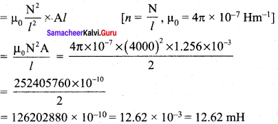
Determine the self-inductance of 4000 turn air-core solenoid of length 2m and diameter 0. 04 m.
Solution:
Length of the air core solenoid, l = 2 m
Diameter, d = 0.04 m
Radius, r = \(\frac { d }{ 2 }\) = 0.02 m
Area of the air core solenoid, A = π2 = 3.14 x (0.02)2 = 1.256 x 10⁻³ m2
Number of Turns, N = 4000 turns
Self inductance, L = µ0n2 Al
Question 10.
A coil of 200 turns carries a current of 4 A. If the magnetic flux through the coil is 6 x 10⁻⁵ Wb, find the magnetic energy stored in the medium surrounding the coil.
Solution:
Number of turns of the coil, N = 200
Current, I = 4 A
Magnetic flux through the coil, Φ = 6 x 10⁻⁵ Wb
Energy stored in the coil, U = \(\frac { 1 }{ 2 }\) LI² = \(\frac { 1 }{ I2}\)
Self inductance of the coil, L = \(\frac { NΦ }{ I }\)
U =\(\frac { 1 }{ 2 }\) \(\frac { NΦ }{ I }\) x I² = \(\frac { 1 }{ 2}\) NΦI = \(\frac { 1 }{ 2}\) x 200 x 6 x 10-5 x 4
U = 2400 x 10-5 = 0.024 J (or) joules.
Question 11.
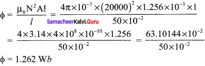
A 50 cm long solenoid has 400 turns per cm. The diameter of the solenoid is 0.04 m. Find the magnetic flux of a turn when it carries a current of 1 A.
Solution:
Length of the solenoid, l = 50 cm = 50 x 10-2 m
Number of turns per cm, N = 400
Number of turns in 50 cm, N = 400 x 50 = 20000
Diameter of the solenoid, d = 0.04 m
Radius of the solenoid, r = \(\frac { d }{ 2}\) = 0.02 m
Area of the solenoid, A = π² = 3.14 x (0.02)² = 1.256 x 10⁻³ m²
Current passing through the solenoid, I = 1 A
Magnetic fluex,
Question 12.
A coil of 200 turns carries a current of 0.4 A. If the magnetic flux of 4 mWb is linked with the coil, find the inductance of the coil.
Solution:
Number of turns, N = 200; Current, I = 0.4 A
Magnetic flux linked with coil, Φ = 4 mWb = 4 x 10⁻³ Wb
Induction of the coil, L = \(\frac { NΦ }{ I }\) = \(\frac {{ 200 × 4 × 10 }^{-3}}{ 0.4 }\) = \(\frac {{ 800 × 10 }^{-3}}{ 0.4 }\) 2 H
Question 13.
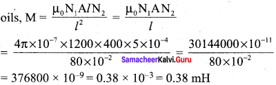
Two air core solenoids have the same length of 80 cm and same cross-sectional area 5 cm². Find the mutual inductance between them if the number of turns in the first coil is 1200 turns and that in the second coil is 400 turns.
Solution:
Length of the solenoids, l = 80 cm = 8 x 10⁻² m
Cross sectional area of the solenoid, A = 5 cm2 = 5 x 10⁻⁴ m2
Number of turns in the Ist coil, N1 = 1200
Number of turns in the IInd coil, N2 = 400
Mutual inductance between the two coils,
Question 14.
A long solenoid having 400 turns per cm carries a current 2A. A 100 turn coil of cross sectional area 4 cm2 is placed co-axially inside the solenoid so that the coil is in the field produced by the solenoid. Find the emf induced in the coil if the current through the solenoid reverses its direction in 0.04 sec.
Solution:
Number of turns of long solenoid per cm =\(\frac { 400 }{{10}^{ -2 }}\); N2 = 400 x 102
Number of turns inside the solenoid, N2 = 100
Cross-sectional area of the coil, A = 4 cm2 = 4 x 10⁻⁴ m2
Current through the solenoid, I = 2A; time, t = 0.04 s
Induced emf of the coil, e = -M \(\frac { dI }{ dt }\)
Mutual inductance of the coil,
Induced emf of the coil,
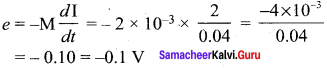
The current through the solenoid reverse its direction if the induced emf, e = -0.2 V
Question 15.
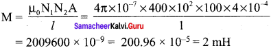
A 200 turn coil of radius 2 cm is placed co-axially within a long solenoid of 3 cm radius. If the turn density of the solenoid is 90 turns per cm, then calculate mutual inductance of the coil.
Solution:
Number of turns of the solenoid, N2 = 200
Radius of the solenoid, r = 2cm = 2 x 10² m
Area of the solenoid, A = πr2= 3.14 x (2 x 10-2)2 = 1.256 x 10⁻³ m2
Turn density of long solenoid per cm, N1 = 90 x 102
Mutual inductance of the coil,
![]()
= 283956.48 x 10-8 ⇒ M = 2.84 mH
Question 16.
The solenoids S1 and S2 are wound on an iron-core of relative permeability 900. The area of their cross-section and their length are the same and are 4 cm2 and 0.04 m, respectively. If the number of turns in S1 is 200 and that in S2 is 800, calculate the mutual inductance between the coils. The current in solenoid 1 is increased from 2A to 8A in 0.04 second. Calculate the induced emf in solenoid 2.
Solution:
Relative permeability of iron core, μr = 900
Number of turns of solenoid S1, N1 = 200
Number of turns of solenoid S2, N2 = ‘800
Area of cross section, A = 4 cm2 = 4 x 10⁻⁴ m2
Length of the solenoid S1, l1 = 0.04 m
current, I =I2 – I1 = 8 – 2 = 6A
time taken, t = 0.04 second
emf induced in solenoid S2 e = -M \(\frac { dI }{ dt }\)
Mutual inductance between the two coils, M = \(\frac{\mu_{0} \mu_{r} N_{1} N_{2} A}{l}\)
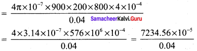
M = 180864 x 10-5 = 1.81 H
Emf induced in solenoid S2, e = -M\(\frac { dI }{ dt }\) = -1.81 x \(\frac { 6 }{ 0.04 }\)
Magnitude of emf, e = 271.5 V
Question 17.
A step-down transformer connected to main supply of 220 V is made to operate 11 V, 88 W lamp. Calculate (i) Transformation ratio and (ii) Current in the primary.
Solution:
Voltage in primary coil, Vp = 220 V
Voltage in secondary coil, Vs = 11 V
Output power = 88 W
(i) To find transformation ratio, k = \(\frac {{ V }_{ s }}{{ V }_{ p }}\) = \(\frac { 11 }{ 220 }\) = \(\frac { 1 }{ 20 }\)
(ii) Current in primary, Ip = \(\frac {{ V }_{ s }}{{ V }_{ p }}\) x Is
So, Is = ?
Outputpower = Vs Is
⇒ 88 = 11 x Is
Is = \(\frac { 88 }{ 11 }\) = 8A
Therefore, Ip = \(\frac {{ V }_{ s }}{{ V }_{ p }}\) x Is = \(\frac { 11 }{ 220 }\) x 8 = 0.4 A
Question 18.
A 200V/120V step-down transformer of 90% efficiency is connected to an induction stove of resistance 40 Ω. Find the current drawn by the primary of the transformer.
Solution:
Primary voltage, Vp = 200 V
Secondary voltage, Vs = 120 V
Efficiency, η = 90%
Secondary resistance, Rs = 40 Ω
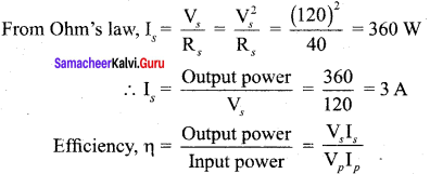
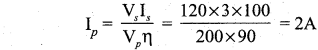
Current drawn by the primary of the transformc, Ip = \(\frac {{ V }_{ s }}{{ R }_{ s }}\) x Is
Output power = Vs Is
Question 19.
The 300 turn primary of a transformer has resistance 0.82 Ω and the resistance of its secondary of 1200 turns is 6.2 Ω. Find the voltage across the primary if the power output from the secondary at 1600V is 32 kW. Calculate the power losses in both coils when the transformer efficiency is 80%.
Solution:
Efficiency, η = 80% = \(\frac { 80 }{ 100 }\)
Number of turns in primary, Np = 300
Number of turns in secondary, Ns = 1200
Resistance in primary, Rp = 0.82 Ω
Resistance in secondary, Rs = 6.2 Ω
Secondary voltage, Vs = 1600 V
Output power = 32 kW
Output power = Vs Is
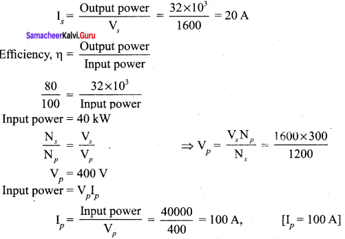
Power loss in primary = \({ { I }_{ p }^{ 2 }{ R }_{ p } }\) = (100)² x 0.82 = 8200 = 8.2 kW
Power loss in secondary = \({ { I }_{ s }^{ 2 }{ R }_{ s } }\) = (20)² x 6.2 = 2480 = 2.48 kW
Question 20.
Calculate the instantaneous value at 60°, average value and RMS value of an alternating current whose peak value is 20 A.
Solution:
Peak value of current, Im = 20 A
Angle, θ = 60° [θ = ωt]
(i) Instantaneous value of current,
i = Im sin ωt = Im sin θ
= 20 sin 60° = 20 x \(\frac { √3 }{ 2 }\) = 10√3 = 10 x 1.732
i = 17.32 A
(ii) Average value of current,
Iav = \(\frac {{ 2I }_{m}}{ π }\) = \(\frac { 2 × 20 }{ 3.14 }\)
Iav = 12.74 A
(iii) RMS value of current,
IRMS = 0.707 Im
or \(\frac{\mathrm{I}_{\mathrm{m}}}{\sqrt{2}}\) = 0.707 x 20
IRMS = 14. 14 A
Samacheer Kalvi 12th Physics Electromagnetic Induction and Alternating Current Conceptual Questions
Question 1.
A graph between the magnitude of the magnetic flux linked with a closed loop and time is given in the figure. Arrange the regions of the graph in ascending order of the magnitude of induced emf in the loop.
Answer:
According to electromagnetic induction, induced emf,
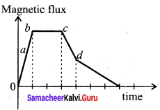
e = \(\frac { dΦ }{ dt }\)
Ascending order of induced emf from the graphical representation is b < c < d < a.
Question 2.
Using Lenz’s law, predict the direction of induced current in conducting rings 1 and 2 when current in the wire is steadily decreasing.
Answer:
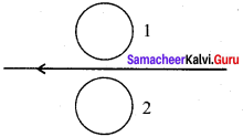
According to Lenz’s law, a current will be induced in the coil which will produce a flux in the opposite direction.
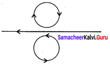
If the current decreases in the wire, the induced current flows in ring 1 in clockwise direction, the induced current flows in ring 2 in anti-clockwise direction.
Question 3.
A flexible metallic loop abed in the shape of a square is kept in a magnetic field with its plane perpendicular to the field. The magnetic field is directed into the paper normally. Find the direction of the induced current when the square loop is crushed into an irregular shape as shown in the figure.
Answer:
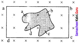
The magnetic flux linked with the wire decreases due to decrease in area of the loop. The induced emf will cause current to flow in the direction. So that the wire is pulled out ward direction from all sides. According to Fleming’s left hand rule, force on wire will act outward i direction from all sides.
Question 4.
Predict the polarity of the capacitor in a closed circular loop when two bar magnets are moved as shown in the figure.
Answer:
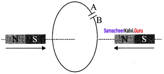
When magnet 1 is moved with its South pole towards to the coil, emf is induced in the coil as the magnetic flux through the coil changes. When seeing from the left hand side the direction of induced current appears to be clockwise. When seeing from the right hand side the direction of induced current appears to be anti-clockwise. In capacitor, plate A has positive polarity and plate B has negative polarity.
Question 5.
In series LC circuit, the voltages across L and C are 180° out of phase. Is it correct? Explain.
Answer:
In series LC circuit, the voltage across the capacitance lag the current by 90° while the voltage across the inductance lead the current by 90°. This makes the inductance and capacitance voltages 180° out of phase.
Question 6.
When does power factor of a series RLC circuit become maximum?
Answer:
For a series LCR circuit, power factor is
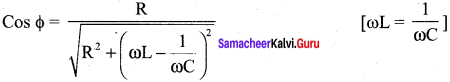
For purely resistive, Φ = 0°, cos 0° = 1
Thus the power factor assumes the maximum value for a purely resistive circuit.
Question 7.
Draw graphs showing the distribution of charge in a capacitor and current through an inductor during LC oscillations with respect to time. Assume that the charge in the capacitor is maximum initially.
Answer:
For a capacitor, the graph between charge and time.
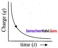
The charge decays exponentially decreases with time.
Samacheer Kalvi 12th Physics Electromagnetic Induction and Alternating Current Additional Questions solved
I Choose The Correct Answer
Question 1.
A coil of area of cross section 0.5 m2 with 10 turns is in a plane which is perpendicular to an uniform magnetic field of 0.2 Wb/m2. The flux through the coil is –
(a) 100 Wb
(b) 10 Wb
(c) 1 Wb
(d) zero
Answer:
(c) 1 Wb
Hint:
Φ = NBA cos θ
= 10 x 0.2 x 0.5 x cos 0° = 1 Wb
Question 2.
A rectangular coil of 100 turns and size 0.1 m x 0.05 m is placed perpendicular to a magnetic field of 0.1 T. If the field drops to 0.05 T in 0.05 s, the magnitude of the emf induced in the coil is-
(a) 0.5 V
(b) 0.75 V
(c) 1.0 V
(d) 1.5 V
Answer:
(a) 0.5 V
Hint:
![]()
ε = 0.5 V
Question 3.
A wire of length 1 m moves with a speed of 10 ms-1 perpendicular to a magnetic field. If the emf induced in the wire is 1 V, the magnitude of the field is-
(a) 0.01 T
(b) 0.1 T
(c) 0.2 T
(d) 0.02 T
Answer:
(b) 0.1 T
Hint:
ε = Blv
⇒ B = \(\frac { ε }{ lv }\) = \(\frac { 1 }{ 1 × 10 }\) = 0.02 T
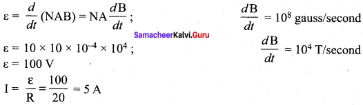
Question 4.
A coil of area 10 cm2, 10 ms-1 turns and resistance 20 Ω is placed in a magnetic field directed perpendicular to the plane of the coil and changing at the rate of 108 gauss/second. The induced current in the coil will be-
(a) 5 A
(b) 0.5 A
(c) 0.05 A
(d) 50 A
Answer:
(a) 5 A
Hint:
Question 5.
A coil of cross sectional area 400 cm2 having 30 turns is making 1800 rev/min in a magnetic field of IT. The peak value of the induced emf is-
(a) 113 V
(b) 226 V
(c) 339 V
(d) 452 V
Answer:
(b) 226 V
Hint:
εm = NBA ω = 30 x 1 x 400 x 10-4 x 30 x 2π
= 226 V
Question 6.
Eddy currents are produced in a material when it is-
(a) heated
(b) placed in a time varying magnetic field
(c) placed in an electric field
(d) placed a uniform magnetic field
Answer:
(b) placed in a time varying magnetic field
Question 7.
An emf of 5 V is induced in an inductance when the current in it changes at a steady rate from 3 A to 2 A in 1 millisecond. The value of inductance is-
(a) 5 mH
(b) 5 H
(c) 5000 H
(d) zero
Answer:
(a) 5 mH
Question 8.
Faraday’s law of electromagnetic induction is related to the-
(a) Law of conservation of charge
(b) Law of conservation of energy
(c) Third law of motion
(d) Law of conservation of angular momentum
Answer:
(b) Law of conservation of energy
Question 9.
The inductance of a coil is proportional to-
(a) its length
(b) the number of turns
(c) the resistance of the coil
(d) square of the number of turns
Answer:
(d) square of the number of turns
Question 10.
When a direct current ‘i’ is passed through an inductance L, the energy stored is-
(a) Zero
(b) Li
(c) \(\frac { 1 }{ 2 }\) Li2
(d) \(\frac {{ L }^{ 2 }}{2i}\)
Answer:
(c) \(\frac { 1 }{ 2 }\) Li2
Question 11.
A coil of area 80 cm2 and 50 turns is rotating with 2000 revolutions per minute about an axis perpendicular to a magnetic field of 0.05 T. The maximum value of the emf developed in it is-
(a) 2000 πV
(b) \(\frac { 10π }{ 3 }\) V
(c) \(\frac { 4π }{ 3 }\)V
(d) \(\frac { 2 }{ 3 }\) V
Answer:
(c) \(\frac { 4π }{ 3 }\)V
Hint:
ε = NBA ω = 50 x 0.05 x 80 x 10-4 x \(\frac { 2π × 2000 }{ 60 }\) = \(\frac { 4π }{ 3 }\)V
Question 12.
The direction of induced current during electro magnetic induction is given by-
(a) Faraday’s law
(b) Lenz’s law
(c) Maxwell’s law
(d) Ampere’s law
Answer:
(b) Lenz’s law
Question 13.
AC power is transmitted from a power house at a high voltage as-
(a) the rate of transmission is faster at high voltages
(b) it is more economical due to less power loss
(c) power cannot be transmitted at low voltages
(d) a precaution against theft of transmission lines
Answer:
(b) it is more economical due to less power loss
Question 14.
In a step-down transformer the input voltage is 22 kV and the output voltage is 550 V. The ratio of the number of turns in the secondary to that in the primary is-
(a) 1 : 20
(b) 20 : 1
(c) 1 : 40
(d) 40 : 1
Answer:
(c) 1 : 40
Hint:
\(\frac {{ N }_{ s }}{{ N }_{ p }}\) = \(\frac {{ V }_{ s }}{{ V }_{ p }}\) = \(\frac { 550 }{ 22000 }\) = \(\frac { 1 }{ 40 }\)
Question 15.
The self-inductance of a coil is 5 H. A current of 1 A changes to 2 A within 5 s through the coil. The value of induced emf will be-
(a) 10 V
(b) 0.1 V
(c) 1.0 V
(d) 100 V
Answer:
(c) 1.0 V
Hint:
Question 16.
The low-loss transformer has 230 V applied to the primary and gives 4.6 V in the secondary. The secondary is connected to a load which draws 5 amperes of current. The current (in amperes) in the primary is-
(a) 0.1 A
(b) 1.0 A
(c) 10 A
(d) 250 A
Answer:
(a) 0.1 A
Hint:
Ip = \(\frac {{ V }_{ s }{ I }_{ s }}{{ V }_{ p }}\) = \(\frac { 4.6 × 5 }{ 230 }\) = 0.1A
Question 17.
A coil is wound on a frame of rectangular cross-section. If all the linear dimensions of the frame are increased by a factor 2 and the number of turns per unit length of the coil remains the same. Self-inductance of the coil increases by a factor of-
(a) 4
(b) 8
(c) 12
(d) 16
Answer:
(b) 8
Hint:
If all the linear dimensions are doubled, the cross-sectional are a becomes eight times. Therefore, the flux produced by a given current will become eight times. Hence, the selfinductance increases by a factor of 8.
Question 18.
If N is the number of turns in a coil, the value of self-inductance varies as-
(a) N°
(b) N
(c) N2
(d) N-2
Answer:
(c) N2
Hint:
According to self inductance of long solenoid
L = \(\frac{\mu_{0} \mathrm{N}^{2} \mathrm{A}}{l}\)
⇒ L ∝ N2
Question 19.
A magnetic field 2 x 10⁻² T acts at right angles to a coil of area 100 cm2 with 50 turns. The average emf induced in the coil will be 0.1 V if it is removed from the field in time.
(a) 0.01 s
(b) 0.1 s
(c) 1 s
(d) 10 s
Answer:
(b) 0.1 s
Hint:
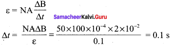
Question 20.
Number of turns in a coil is increased from 10 to 100. Its inductance becomes-
(a) 10 times
(b) 100 times
(c) 1/10 times
(d) 25 times
Answer:
(a) 10 times
Question 21.
The north pole of a magnet is brought near a metallic ring as shown in the figure. The direction of induced current in the ring, as seen by the magnet is-
(a) anti-clockwise
(b) first anti-clockwise and then clockwise
(c) clockwise
(d) first clockwise and then anti-clockwise
Answer:
(a) anti-clockwise
Question 22.
Quantity that remains unchanged in a transformer is-
(a) voltage
(b) current
(c) frequency
(d) none of these
Answer:
(c) frequency
Question 23.
The core of a transformer is laminated to reduce.
(a) Copper loss
(b) Magnetic loss
(c) Eddy current loss
(d) Hysteresis loss
Answer:
(c) Eddy current loss
Question 24.
Which of the following has the dimension of time?
(a) LC
(b) \(\frac { R }{ L }\)
(c) \(\frac { L }{ R }\)
(d) \(\frac { C }{ L }\)
Answer:
(c) \(\frac { L }{ R }\)
Question 25.
A coil has a self-inductance of 0.04 H. The energy required to establish a steady-state current of 5 A in it is-
(a) 0.5 J
(b) 1.0 J
(c) 0.8 J
(d) 0.2 J
Answer:
(a) 0.5 J
Question 26.
Alternating current can be measured by
(a) moving coil galvanometer
(b) hot wire ammeter
(c) tangent galvanometer
(d) none of the above
Answer:
(b) hot wire ammeter
Question 27.
In an LCR circuit, the energy is dissipated in-
(a) R only
(b) R and L only
(c) R and C only
(d) R, L and C
Answer:
(a) R only
Question 28.
A 40 Ω electric heater is connected to 200 V, 50 Hz main supply. The peak value of the electric current flowing in the circuit is approximately-
(a) 2.5 A
(b) 5 A
(c) 7 A
(d) 10 A
Answer:
(c) 7 A
Hint:
I0 = \(\frac {{ V }_{0}}{ R }\) = \(\frac{200 \sqrt{2}}{40}\) 5 √2 ≈ 7A
Question 29.
The rms value of an alternating current, which when passed through a resistor produces heat three times of that produced by a direct current of 2 A in the same resistor, is-
(a) 6 A
(b) 3 A
(c) 2 A
(d) 2√3 A
Answer:
(d) 2√3 A
Hint:
\({ I }_{ rms }^{ 2 }\)R = 3(22R) (or) Irms = 2√3 A
Question 30.
An inductance, a capacitance and a resistance are connected in series across a source of alternating voltages. At resonance, the applied voltage and the current flowing through the circuit will have a phase difference of-
(a) \(\frac { π }{ 4 }\)
(b) zero
(c) π
(d) \(\frac { π }{ 2 }\)
Answer:
(b) zero
Question 31.
In an AC circuit, the rms value of the current Irms, is related to the peak current I0 as-
(a) Irms = \(\frac {{I}_{0}}{ π }\)
(b) Irms = \(\frac {{I}_{0}}{ √2 }\)
(c) Irms = √2 I0
(d) Irms = πI0
Answer:
(b) Irms = \(\frac {{I}_{0}}{ √2 }\)
Question 32.
The impedance of a circuit consists of 3 Ω resistance and 4 Ω resistance. The power factor of the circuit is
(a) 0.4
(b) 0.6
(c) 0.8
(d) 1.0
Answer:
(b) 0.6
Hint:
tan Φ = \(\frac { 4 }{ 3 }\).
Power factor = cos Φ = \(\frac { 3 }{ 5 }\) = 0.06
Question 33.
The reactance of a capacitance at 50 Hz is 5 Ω. Its reactance at 100 Hz will be-
(a) 5 Ω
(b) 10 Ω
(c) 20 Ω
(d) 2.5 Ω
Answer:
(d) 2.5 Ω.
Question 34.
In a LCR AC circuit off resonance, the current-
(a) is always in phase with the voltage
(b) always lags behind the voltage
(c) always leads the voltage
(d) may lead or lag behind the voltage
Answer:
(d) may lead or lag behind the voltage
Question 35.
The average power dissipation in a pure inductance L, through which a current I0 sin ωt is flowing is-
(a) \(\frac { 1 }{ 2 }\) L\({ I }_{ 0 }^{ 2 }\)
(b) L\({ I }_{ 0 }^{ 2 }\)
(c) 2 L\({ I }_{ 0 }^{ 2 }\)
(d) zero
Answer:
(d) zero
Question 36.
The power in an AC circuit is given by P = Vrms Irms cos Φ. The value of the power factor cos Φ in series LCR circuit at resonance is-
(a) zero
(b) 1
(c) \(\frac { 1 }{ 2 }\)
(d) \(\frac { 1 }{ √2 }\)
Answer:
(b) 1
Hint:
Question 37.
In an AC circuit with voltage V and current I, the power dissipated is-
(a) VI
(b) \(\frac { 1 }{ 2 }\) VI
(c) \(\frac { 1 }{ √2 }\) VI
(d) depends on the phase difference between I and V
Answer:
(d) depends on the phase difference between I and V
Question 38.
In an AC circuit containing only capacitance, the current-
(a) leads the voltage by 180°
(b) remains in phase with the voltage
(c) leads the voltage by 90°
(d) lags the voltage by 90°
Answer:
(c) leads the voltage by 90°
Question 39.
In a series LCR circuit R = 10 Ω and the impedance Z = 20 Ω. Then the phase difference between the current and the voltage is-
(a) 60°
(b) 30°
(c) 45°
(d) 90°
Answer:
(c) 60°
Hint:
cos Φ = \(\frac { R }{ Z }\) = \(\frac { 10 }{ 20 }\) = \(\frac { 1 }{ 2 }\)
⇒ Φ = 60°
Question 40.
What is the value of inductance L for which the current is maximum in a series LCR circuit with C = 10 μF and ω = 1000 s-1?
(a) 1 mH
(b) 10 mH
(c) 100 mH
(d) Cannot be calculated unless R is known
Answer:
(c) 100 mH
Hint:
L = \(\frac { 1 }{ { \omega }^{ 2 }C } \) = \(\frac{1}{(1000)^{2} \times 10 \times 10^{-6}}\) = 0.1 H = 100 mH
II Fill in the Blanks
Question 1.
Electromagnetic induction is used in …………….
Answer:
transformer and AC generator
Question 2.
Lenz’s Law is in accordance with the law of …………….
Answer:
conservation of energy.
Question 3.
The self-inductance of a straight conductor is …………….
Answer:
zero
Question 4.
Transformer works on …………….
Answer:
AC only
Question 5.
The power loss is less in transmission lines when …………….
Answer:
voltage is more but current is less
Question 6.
The law that gives the direction of the induced current produced in a circuit is …………….
Answer:
Lenz’s law
Question 7.
Fleming’s right hand rule is otherwise called …………….
Answer:
generator rule
Question 8.
Unit of self-inductance is …………….
Answer:
Henry
Question 9.
The mutual induction is very large, if the two coils are wound on …………….
Answer:
soft iron core
Question 10.
When the coil is in vertical position, the angle between the normal to the plane of the coil and magnetic field is …………….
Answer:
zero
Question 11.
The emf induced by changing the orientation of the coil is ……………. in nature.
Answer:
sinusoidal
Question 12.
In a three phase AC generator, the three coils are inclined at an angle of …………….
Answer:
120°
Question 13.
The emf induced in each of the coils differ in phase by …………….
Answer:
120°
Question 14.
A device which converts high alternating voltage into low alternating voltage and vice versa is …………….
Answer:
transformer
Question 15.
For an ideal transformer efficiency η is …………….
Answer:
1
Question 16.
The alternating emf induced in the coil varies …………….
Answer:
periodically in both magnitude and direction
Question 17.
For direct current, inductive reactance is …………….
Answer:
zero
Question 18.
In an inductive circuit the average power of sinusoidal quantity of double the frequency over a complete cycle is …………….
zero
Question 19.
For direct current, the resistance offered by a capacitor is …………….
Answer:
infinity
Question 20.
In a capacitive circuit, power over a complete cycle is …………….
Answer:
zero
Question 21.
Q-factor measures the …………….in resonant circuit
Answer:
selectivity
Question 22.
Voltage drop across inductor and capacitor differ in phase by …………….
Answer:
180°
Question 23.
Angular resonant frequency (co) is …………….
Answer:
\(\frac { 1 }{ \sqrt { LC } } \)
Question 24.
A circuit will have flat resonance if its Q-value is …………….
Answer:
low
Question 25.
The average power consumed by the choke coil over a complete cycle is …………….
Answer:
zero
III Match the following
Question 1.
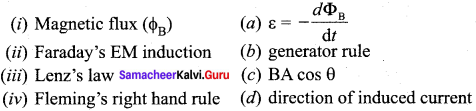
Answer:
(i) → (c)
(ii) → (a)
(iii) → (d)
(iv) → (b)
Question 2.
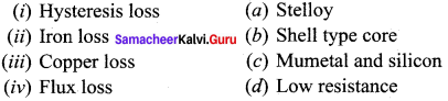
Answer:
(i) → (c)
(ii) → (a)
(iii) → (d)
(iv) → (b)
Question 3.
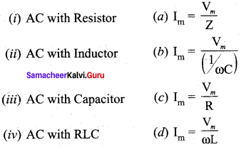
Answer:
(i) → (c)
(ii) → (d)
(iii) → (b)
(iv) → (a)
Question 4.
Type of impedance Phase between voltage and current
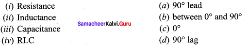
Answer:
(i) → (c)
(ii) → (d)
(iii) → (a)
(iv) → (b)
Question 5.
Energy in two oscillatory systems: (LC oscillator and spring mass system)
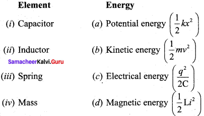
Answer:
(i) → (c)
(ii) → (d)
(iii) → (a)
(iv) → (b)
IV Assertion and reason
(a) If both assertion and reason are true and the reason is the correct explanation of the assertion.
(b) If both assertion and reason are true but reason is not the correct explanation of the assertion.
(c) If assertion is true but reason is false.
(d) If the assertion and reason both are false.
(e) If assertion is false but reason is true.
Question 1.
Assertion: Eddy currents is produced in any metallic conductor when flux is changed around it.
Reason: Electric potential determines the flow of charge.
Answer:
(b) If both assertion and reason are true but reason is not the correct explanation of the assertion.
Solution:
When a metallic conductor is moved in a magnetic field, magnetic flux is “varied. It disturbs the free electrons of the metal and set up an induced emf in it. As there are no free ends of the metal i.e., it will be closed in itself so there will be induced current.
Question 2.
Assertion: Faraday’s laws are consequences of conservation of energy.
Reason: In a purely resistive AC circuit, the current lags behind the emf in phase.
Answer:
(c) If assertion is true but reason is false.
Solution:
According to Faraday’s law, the conversion of mechanical energy into electrical energy is in accordance with the law of conservation of energy. It is also clearly known that in pure resistance, the emf is in phase with the current.
Question 3.
Assertion: Inductance coil are made of copper.
Reason: Induced current is more in wire having less resistance.
Answer:
(a) If both assertion and reason are true and the reason in the correct explanation of the assertion.
Solution:
Inductance coils made of copper will have very small ohmic resistance.
Question 4.
Assertion: An aircraft flies along the meridian, the potential at the ends of its wings will be the same.
Reason: Whenever there is a change in the magnetic flux, and emf is induced.
Answer:
(e) If assertion is false but reason is true.
Solution:
As the aircraft flies magnetic flux change through its wings due to the vertical component of the Earth’s magnetic field. Due to this, induced emf is produced across the wings of the aircraft. Therefore, the wings of the aircraft will not be at the same potential.
Question 5.
Assertion: In series LCR circuit resonance can take place.
Reason: Resonance takes place if inductance and capacitive reactances are equal and opposite.
Answer:
(a) If both assertion and reason are hue and the reason is the correct explanation of the assertion.
Solution:
At resonant frequency XL = XC
So, Impedance, Z = R (minimum)
Therefore, the current in the circuit is maximum.
Samacheer Kalvi 12th Physics Electromagnetic Induction and Alternating Current Short Answer Questions
Question 1.
Define magnetic flux (ΦB).
The magnetic flux through an area A in a magnetic field is defined as the number of magnetic field lines passing through that area normally and is given by the equation,
![]()
Question 2.
Write down the drawbacks of Eddy currents.
Answer:
When eddy currents flow in the conductor, a large amount of energy is dissipated in the form of heat. The energy loss due to the flow of eddy current is inevitable but it can be reduced to a greater extent with suitable measures. The design of transformer core and electric motor armature is crucial in order to minimise the eddy current loss.
To reduce these losses, the core of the transformer is made up of thin laminas insulated from one another while for electric motor the winding is made up of a group of wires insulated from one another. The insulation used does not allow huge eddy currents to flow and hence losses are minimized.
Question 3.
Define the unit of self-inductance.
Answer:
The unit of self-inductance is henry. One henry is defined as the self-inductance of a coil in which a change in current of one ampere per second produces an opposing emf of one volt.
Question 4.
Define mutual inductance in terms of flux and current.
Answer:
The mutual inductance M21 is defined as the flux linkage of the coil 2 when 1A current flows through coil 1.
M21 = \(\frac{\mathrm{N}_{2} \mathrm{\phi}_{21}}{i_{1}}\)
Question 5.
Define mutual inductance in terms of emf and current.
Answer:
Mutual inductance M21 is also defined as the opposing emf induced is the coil 2 when the rate of change of current through the coil 1 is 1 As-1.
M12 = \(\frac{-\varepsilon_{1}}{d i_{2} / d t}\)
Question 6.
List out the advantages of three phase alternator.
Answer:
Three-phase system has many advantages over single-phase system, which is as follows:
(i) For a given dimension of the generator, three-phase machine produces higher power output than a single-phase machine.
(ii) For the same capacity, three-phase alternator is smaller in size when compared to single phase alternator.
(iii) Three-phase transmission system is cheaper. A relatively thinner wire is sufficient for transmission of three-phase power.
Question 7.
Mentions the differences betw een a step up and step down transformer.
Answer:
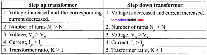
Question 8.
Define efficiency of transformer.
Answer:
The efficiency p of a transformer is defined as the ratio of the useful output power to the input power. Thus
Transformers are highly efficient devices having their efficiency in the range of 96 – 99%. Various energy losses in a transformer will not allow them to be 100% efficient.
Question 9.
What is meant by sinusoidal alternating voltage?
Answer:
If the waveform of alternating voltage is a sine wave, then it is known as sinusoidal alternating voltage, which is given by the relation.
υ = Vm sin ωt
Question 10.
An inductor blocks AC but it allows DC. Why? and How?
Answer:
An inductor L is a closely wound helical coil. The steady DC current flowing through L produces uniform magnetic field around it and the magnetic flux linked remains constant. Therefore there is no self-induction and self-induced emf (back emf). Since inductor behaves like a resistor, DC flows through an inductor.
The AC flowing through L produces time-varying magnetic field which in turn induces self- induced emf (back emf). This back emf, according to Lenz’s law, opposes any change in the current. Since AC varies both in magnitude and direction, its flow is opposed in L. For an ideal inductor of zero ohmic resistance, the back emf is equal and opposite to the applied emf. Therefore L blocks AC.
Question 11.
A capacitor blocks DC but allows AC. Explain.
Answer:
Capacitive reactance, XC = \(\frac { 1 }{ ωC }\) = \(\frac { 1 }{ 2πƒc }\)
where, ƒ = 0, XC = ∞
where, ƒ is the frequency of the ac supply. In a dc circuit ƒ = 0. Hence the capacitive reactance has infinite value for dc and a finite value for ac. In other words, a capacitor serves as a block for dc and offers an easy path to ac.
Question 12.
Why dc ammeter cannot read ac?
Answer:
A dc ammeter cannot read ac because, the average value of ac is zero over a complete cycle.
Question 13.
Write down the applications of series RLC resonant circuit.
Answer:
RLC circuits have many applications like filter circuits, oscillators and voltage multipliers, etc. An important use of series RLC resonant circuits is in the tuning circuits of radio and TV systems. The signals from many broadcasting stations at different frequencies are available in the air. To receive the signal of a particular station, tuning is done.
Question 14.
What is meant by ‘Wattful current’?
Answer:
The component of current (Irms cos Φ) which is in phase with the voltage is called active component. The power consumed by this current = Vrms Irms cos Φ. So that it is also known as ‘Wattful’ current.
Samacheer Kalvi 12th Physics Electromagnetic Induction and Alternating Current Long Answer Questions
Question 1.
Derive an expression for Mutual Inductance between two long co-axial solenoids.
Answer:
Mutual inductance between two long co-axial solenoids:
Consider two long co-axial solenoids of same length 1. The length of these solenoids is large when compared to their radii so that the magnetic field produced inside the solenoids is uniform and the fringing effect at the ends may be ignored. Let A1 and A2 be the area of cross section of the solenoids with A1 being greater than A2. The turn density of these solenoids are n1 and n2 respectively.
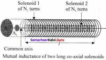
Let i1 be the current flowing through solenoid 1, then the magnetic field produced inside it is
B1 = μ0n1i1.
As the field lines of \(\vec {{ B }_{1}} \) are passing through the area bounded by solenoid 2, the magnetic flux is linked with each turn of solenoid 2 due to solenoid 1 and is given by
![]()
since θ = 0°
The flux linkage of solenoid 2 with total turns N2 is
N2Φ21 = (n2l)(μ0 n1 i1)
since N2 = n2l
N2Φ21 = (μ0 n1 n2 A2l)i1 ….. (1)
From equation of mutual induction
N2Φ21 = M21 i1 …… (2)
Comparing the equations (1) and (2),
M21 = μ0 n1 n2 A2l ….. (3)
This gives the expression for mutual inductance M21 of the solenoid 2 with respect to solenoid 1. Similarly, we can find mutual inductance M21 of solenoid 1 with respect to solenoid 2 as given below.
The magnetic field produced by the solenoid 2 when carrying a current i2 is
B2 = μ0 n2 i2
This magnetic field B2 is uniform inside the solenoid 2 but outside the solenoid 2, it is almost zero. Therefore for solenoid 1, the area A2 is the effective area over which the magnetic field B2 is present; not area A2 Then the magnetic flux Φ12 linked with each turn of solenoid 1 due to solenoid 2 is
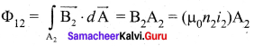
The flux linkage of solenoid 1 with total turns N1 is
[Since N1 = n1l]
[Since N1 Φ12 = M12i2]
N1 Φ12 = (n1l) (μ0 n2 i2) A2
N1 Φ12 = (μ0 n1 n2 A2l) i2
M12i2 = (μ0 n1 n2 A2l) i2
Therefore, we get
∴ M12 = μ0 n1 n2 A2l ……. (4)
From equation (3) and (4), we can write
M12 = M21 = M ……. (5)
In general, the mutual inductance between two long co-axial solenoids is given by
M= μ0 n1 n2 A2l ……. (6)
If a dielectric medium of relative permeability’ pr is present inside the solenoids, then
M = μn1 n2 A2l
or M = μ0 μr n1 n2 A2l
Question 2.
How will you define the unit of mutual-inductance?
Answer:
Unit of mutual inductance:
The unit of mutual inductance is also henry (H).
If iA= 1 A and N2 Φ21 = 1 Wb turns, then M21 = 1 H.
Therefore, the mutual inductance between two coils is said to be one henry if a current of 1A in coil 1 produces unit flux linkage in coil 2.
If \(\frac {{ di }_{1}}{ 2 }\) = 1 As-1 and ε2 = -1V, theen M21 = 1H.
Therefore, the mutual inductance between two coils is one henry if a current changing at the rate of lAs-1 in coil 1 induces an opposing emf of IV in coil 2.
Question 3.
Find out the phase relationship between voltage and current in a pure resister circuit.
Answer:
AC circuit containing pure resistor:
Consider a circuit containing a pure resistor of resistance R connected across an alternating voltage source. The instantaneous value of the alternating voltage is given by
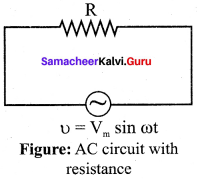
υ = Vm sin ωt ….. (1)
An alternating current i flowing in the circuit due to this voltage, develops a potential drop across R and is given by
VR = iR ……. (2)
Kirchoff’s loop rule states that the algebraic sum of potential differences in a closed circuit is zero. For this resistive circuit,
υ – VR = 0
From equation (1) and (2),
Vm sin ωt = iR
⇒ i = \(\frac {{ V }_{m}}{ R }\) sin ωt
i = Im sin ωt …… (3)
where V\(\frac {{ V }_{m}}{ R }\) = Im the peak value of alternating current in the circuit. From equations (1) and and (3), it is clear that the applied voltage and the current are in phase with each other in a resistive circuit. It means that they reach their maxima and minima simultaneously. This is indicated in the phasor diagram. The wave diagram also depicts that current is in phase with the applied voltage.
Question 4.
Find out the phase relationship between voltage and current in a pure capacitor circuit.
Answer:
AC circuit containing only a capacitor:
Consider a circuit containing a capacitor of capacitance C connected across an alternating voltage source.
The alternating voltage is given by
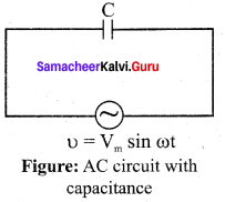
Vm sin ωt …… (1)
Let q be the instantaneous charge on the capacitor. The emf across the capacitor at that instant is \(\frac { q }{ C }\). According to Kirchoff’s loop rule,.
υ = \(\frac { q }{ C }\) = 0
⇒ CVm sin ωt
By the definition of current,
i = \(\frac { dq }{ dt }\) = \(\frac { d }{ dt }\) CVm \(\frac { d }{ dt }\) (sin ωt)
= CVm sin ωt
or i = \(\frac{\frac{\mathrm{V}_{m}}{1}}{\frac{\mathrm{l}}{\mathrm{C} \omega}}\) sin \(\left(\omega t+\frac{\pi}{2}\right)\)
i = Im sin \(\left(\omega t+\frac{\pi}{2}\right)\) ….. (2)
where \(\frac{\frac{\mathrm{V}_{m}}{1}}{\frac{\mathrm{l}}{\mathrm{C} \omega}}\) = Im, the peak value of the alternating current. From equation (1) and (2), it is clear that current leads the applied voltage by π/2 in a capacitive circuit. The wave diagram for a capacitive circuit also shows that the current leads the applied voltage by 90°.
Question 5.
What are LC oscillation? and explain the generation of LC oscillation.
Answer:
Whenever energy is given to a circuit containing a pure inductor of inductance L and a capacitor of capacitance C, the energy oscillates back and forth between the magnetic field of the inductor and the electric field of the capacitor. Thus the electrical oscillations of definite frequency are generated. These oscillations are called LC oscillations.
Generation of LC oscillations:
Let us assume that the capacitor is fully charged with maximum charge Qm at the initial stage. So that the energy stored in the capacitor is maximum and is given by UEm = \(\frac{\mathrm{Q}_{\mathrm{m}}^{2}}{2 \mathrm{C}}\) As there is no current in the inductor, the energy stored in it is zero i.e., UB = 0. Therefore, the total energy is wholly electrical.
The capacitor now begins to discharge through the inductor that establishes current i in clockwise direction. This current produces a magnetic field around the inductor and the energy stored in the inductor is given by UB = \(\frac {{ Li }_{ 2 }}{ 2 }\). As the charge in the capacitor decreases, the energy stored in it also decreases and is given by UE = \(\frac {{ q }_{ 2 }}{ 2C }\). Thus there is a transfer of some part of energy from the capacitor to the inductor. At that instant, the total energy is the sum of electrical and magnetic energies.
When the charges in the capacitor are exhausted, its energy becomes zero i.e., UE = 0. The energy is fully transferred to the magnetic field of the inductor and its energy is maximum. This maximum energy is given by UB = \(\frac{\mathrm{LI}_{\mathrm{m}}^{2}}{2}\) where Im is the maximum current flowing in the circuit. The total energy is wholly magnetic.
Even though the charge in the capacitor is zero, the current will continue to flow in the same direction because the inductor will not allow it to stop immediately. The current is made to flow with decreasing magnitude by the collapsing magnetic field of the inductor. As a result of this, the capacitor begins to charge in the opposite direction. A part of the energy is transferred from the inductor back to the capacitor. The total energy is the sum of the electrical and magnetic energies.
When the current in the circuit reduces to zero, the capacitor becomes frilly charged in the opposite direction. The energy stored in the capacitor becomes maximum. Since the current is zero, the energy stored in the inductor is zero. The total energy is wholly electrical. The state of the circuit is similar to the initial state but the difference is that the capacitor is charged in opposite direction. The capacitor then starts to discharge through the inductor with anti-clockwise current. The total energy is the sum of the electrical and magnetic energies.
As already explained, the processes are repeated in opposite direction. Finally, the circuit returns to the initial state. Thus, when the circuit goes through these stages, an alternating current flows in the circuit. As this process is repeated again and again, the electrical oscillations of definite frequency are generated. These are known as LC oscillations. In the ideal LC circuit, there is no loss of energy. Therefore, the oscillations will continue indefinitely. Such oscillations are called undamped oscillations.
Samacheer Kalvi 12th Physics Electromagnetic Induction and Alternating Current Numerical Problems
Question 1.
A coil has 2000 turns and area 70 cm2. The magnetic field perpendicular to the plane of the coil is 0.3 Wb/m2. The coil takes 0.1 s to rotate through 180°. Then what is the value of induced emf?
Solution:
Magnitude of change in flux,
|∆Φ | = |NBA (cos 180° – cos 0°
= |NBA(-1 – 1)| = |-2 NBA| = |2 NBA|
Where,
N = 2000
B = 0.3 Wb/m2
A = 70 x 10-4 m2
t = 0.1 sec
Induced emf, ε = \(\frac { \left| \Delta \phi \right| }{ \Delta t } \) = \(\frac { 2NBA }{ ∆t }\) = \(\frac {{ 2 × 2000 × 0.3 × 70 × 10 }^{-4}}{ 0.1 }\)
ε = 84 V
Question 2.
A rectangular loop of sides 8 cm and 2 cm is lying in a uniform magnetic field of magnitude 0.5 T with its plane normal to the field. The field is now gradually reduced at the rate of 0.02 T/s. If the resistance of the loop is 1.6 Ω, then find the power dissipated by the loop as heat.
Solution:
Induced emf, |ε| = \(\frac { dΦ }{ dt } \) = A \(\frac { dB }{ dt } \) = 8 × 2 × 10-4 × 0.02
ε = 3.2 × 10⁻⁵ V
Induced current, I = \(\frac { ε }{ R } \) = 2 × 10⁻⁵ A
Power loss = I2R = 4 × 10-10 × 1.6 = 6.4 × 10⁻¹⁰ W
Question 3.
A current of 2 A flowing through a coil of 100 turns gives rise to a magnetic flux of 5 x 10⁻⁵ Wb per turn. What is the magnetic energy associated with the coil?
Solution:
Self inductance of coil, L = \(\frac { NΦ }{ I } \) = \(\frac {{ 100 × 5 × 10 }^{-3}}{ 2 } \)
= 2.5 × 10⁻³ H
Magnetic energy associated with inductance,
U = \(\frac { 1 }{ 2 }\) LI2 = \(\frac { 1 }{ 2 }\) × 2.5 × 10-3 × (2)2
= \(\frac { 1 }{ 2 }\) × 2.5 × 10-3 × 4 = 5 × 10⁻³ J
Question 4.
A transformer is used to light a 140 W, 24 V bulb from a 240 V AC mains. The current in the main cable is 0.7 A. Find the efficiency of the transformer.
Solution:
η = \(\frac { 140 }{ 240 × 0.7 }\) × 100 = 83.3%
Question 5.
In an ideal step up transformer the turns ratio is 1 : 10. A resistance of 200 ohm connected across the secondary is drawing a current of 0.5 A. What are the primary voltage and current?
Solution:
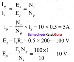
Primary current, Ip = 5 A
Promary voltage, Ep = 10 V
Question 6.
A capacitor of capacitance 2 μF is connected in a tank circuit oscillating with a frequency of 1 kHz. If the current flowing in the circuit is 2 mA, then find the voltage across the capacitor.
Solution:
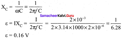
Question 7.
An ideal inductor takes a current of 10 A when connected to a 125 V, 50 Hz AC supply. A pure resistor across the same source takes 12.5 A. If the two are connected in series across a 100 √2 V, 40 Hz supply, then calculate the current through the circuit.
Solution:
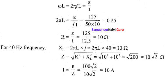
Question 8.
An LCR series circuit containing a resistance of 120 Ω. has angular resonance frequency 4 x 10⁵ rad s-1. At resonance the voltages across resistance and inductance are 60 V and 40 V, respectively. Find the values of L and C.
Solution:
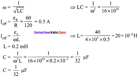
Question 9.
A coil of inductive reactance 31 Ω has a resistance of 8 Ω. It is placed in series with a capacitor of capacitance reactance 25 Ω. The combination is connected to an ac source of 110 volt. Find the power factor of the circuit.
Solution:
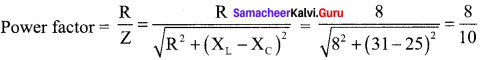
Power faactor = 0.8
Question 10.
The power factor of an RL circuit is \(\frac { 1 }{ √2 }\). If the frequency of AC is doubled, what will be the power factor?
Solution:
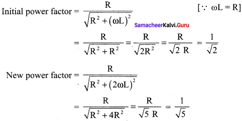
Question 11.
The instantaneous value of alternating current and voltage are given as i = \(\frac { 1 }{ √2 }\) sin (100 πt) A and e = \(\frac { 1 }{ √2 }\) sin(100 πt + \(\frac { π }{ 3 }\)) volt. Find the average power in watts consumed in the circuit.
Solution:
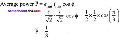
Common Errors and its Rectifications:
Common Errors:
- Students sometimes may confuse the peak current and instantaneous value of current and emf.
- They may confuse in the area of R, L and C with AC. The relation between current and induced emf.
Rectifications:
- Instantaneous current, i = I0 sin tot Peak current, I0 = √2 Irms Instantaneous emf, e = E0 sin cor Peak emf, E0 = √2 Erms
- In Inductor: current is \(\frac { π }{ 2 }\) rad less than that of emf.
In Resistor: current and emf are same phase.
In Capacitor: current is \(\frac { π }{ 2 }\) rad greater than that of emf.
We believe that the shared knowledge about Tamilnadu State Board Solutions for 12th Physics Chapter 4 Electromagnetic Induction and Alternating Current Questions and Answers learning resource will definitely guide you at the time of preparation. For more details visit Tamilnadu State Board Solutions for 12th Physics Solutions and for more information ask us in the below comments and we’ll revert back to you asap.